 ChipApex | Global Electronic Components Supplier
SEARCH
Search Product
Search Post
— IC芯片 | 连接器 | 传感器 | 被动器件 —
Search productSearch post
— IC芯片 | 连接器 | 传感器 | 被动器件 —
Consult the customer manager about the wholesale price.
consultation hotline:86-132-6715-2157
email:[email protected]
Contact the product manager for consultation. One-stop consultation is available.
Do you want a lower wholesale price? Please send us your inquiry and we will reply immediately.
The 15M392J is a fixed inductor manufactured by Gowanda Electronics, classified as an unshielded molded RF coil with axial lead configuration. It provides an inductance of 39 µH and supports a maximum current rating of 176 mA. The component features a maximum DC resistance of 2.6 Ohms and maintains a minimum Q factor of 60 at a test frequency of 2.5 MHz. Designed for commercial off-the-shelf applications, this part integrates standard axial mounting for integration into electronic circuits requiring specific RF characteristics.
Verify the current manufacturing status before procurement, as available sources indicate this product may be discontinued. Confirm availability through authorized distributors or alternative sourcing channels if new production units are required. Ensure that the axial lead pitch and physical dimensions meet the target PCB layout requirements. Validate that the 176 mA current rating and 2.6 Ohm resistance align with system power constraints.
Select the 15M392J when an unshielded axial inductor with 39 µH inductance is required for COTS designs. Consider its 176 mA current limit and 2.6 Ohm resistance for power budget calculations. The specified Q factor of 60 at 2.5 MHz indicates suitability for moderate frequency RF tasks. Evaluate space constraints for axial leads and ensure shielding requirements do not conflict with the unshielded design.
Gowanda Electronics specializes in high-performance magnetic components for demanding environments, including aerospace and medical fields. The 15M392J belongs to their line of fixed inductors, which include shielded and unshielded variants in surface mount and axial configurations. This model represents a standard molded RF coil designed for reliable operation in commercial applications where specific inductive values are critical.
Public sources indicate the 15M392J may be discontinued. Potential substitutes include other 39 µH axial inductors from Gowanda such as the 15M391 series, though exact electrical equivalence must be verified against datasheets. Cross-reference parameters like current rating, DC resistance, and Q factor to ensure functional compatibility in the target application.
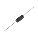 15M392J
The activity of extra discounts on wholesale prices is in full swing…
Please fill in your contact information and we will send you the latest wholesale price list.




