 ChipApex | Global Electronic Components Supplier
SEARCH
Search Product
Search Post
— IC芯片 | 连接器 | 传感器 | 被动器件 —
Search productSearch post
— IC芯片 | 连接器 | 传感器 | 被动器件 —
Consult the customer manager about the wholesale price.
consultation hotline:86-132-6715-2157
email:[email protected]
Contact the product manager for consultation. One-stop consultation is available.
Do you want a lower wholesale price? Please send us your inquiry and we will reply immediately.
The onsemi 1N5354B is a silicon Zener voltage regulator diode with a nominal breakdown voltage of 17 V and a maximum steady-state power dissipation of 5 W. It features a ±5% tolerance, a test current (IZT) of 70 mA, and a maximum Zener impedance (ZZT) of 2.5 Ω at the test current. The device operates within a junction temperature range of -65°C to +200°C, with a DC limit of 150°C. It utilizes an axial lead plastic package (CASE 017AA/DO-201AE) with isolated terminals.
Verify that the ordered part number matches the specific JEDEC designation required for your circuit design. Confirm package availability options, such as box or tape-and-reel configurations, align with your assembly process. Ensure compliance with RoHS directives if applicable by checking for the 'G' suffix indicating lead-free packaging. Review the datasheet thermal derating curves to confirm suitability for your specific ambient temperature conditions.
Select this component when a precise 17 V reference with tight tolerance is necessary. Consider the 5 W power rating and thermal resistance characteristics for heat dissipation requirements. Evaluate the low leakage current and impedance specifications for signal integrity needs. Verify that the axial lead format fits the mechanical constraints of the target printed circuit board layout.
This device belongs to the 1N53 Series, a comprehensive family of 5 Watt Zener diodes manufactured by onsemi. The series spans a wide voltage range from 3.3 V to 200 V, offering consistent performance across various breakdown voltages. All members share the same Surmetic 40 axial lead package and silicon-oxide passivation technology, ensuring uniform reliability and mounting characteristics throughout the product line.
Cross-reference with other manufacturers' 1N5354B equivalents to ensure pinout and electrical parameter compatibility. Verify that substitute components meet the same 5 W power dissipation and ±5% voltage tolerance requirements. Check for identical package dimensions to maintain mechanical fit without redesigning the PCB footprint.
The device supports a peak surge current rating of up to 180 W for an 8.3 ms pulse width, as specified in the electrical characteristics table.
Polarity is identified by a cathode band marked on the external surface of the plastic case.
The junction-to-lead thermal resistance is typically 25 °C/W, measured at a lead length of 3/8 inch.
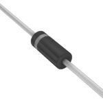 1N5354B
The activity of extra discounts on wholesale prices is in full swing…
Please fill in your contact information and we will send you the latest wholesale price list.





