ChipApex | Global Electronic Components Supplier
SEARCH
Search Product
Search Post
— IC芯片 | 连接器 | 传感器 | 被动器件 —
Search productSearch post
— IC芯片 | 连接器 | 传感器 | 被动器件 —
Consult the customer manager about the wholesale price.
consultation hotline:86-132-6715-2157
email:[email protected]
Contact the product manager for consultation. One-stop consultation is available.
Do you want a lower wholesale price? Please send us your inquiry and we will reply immediately.
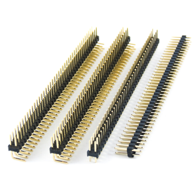
The Oupiin 2011-2X20G00SB is a board connector featuring 40 contacts arranged in two rows. It utilizes male pins with a 0.1 inch (2.54mm) pitch for reliable signal transmission. The component employs a straight, through-hole solder terminal configuration for secure PCB mounting. Gold plating on the contact surfaces ensures low resistance and corrosion resistance. The design incorporates locking features to maintain connection stability during operation.
Verify that the specific part number matches the required dual-row, 40-contact specification. Confirm the straight orientation and through-hole mounting style align with the target PCB layout. Ensure compatibility with mating female sockets regarding the 0.1 inch pitch dimension. Check for any specific packaging or reel requirements if automated assembly is planned. Validate that the gold plating thickness meets the application's durability standards.
Select this component when a dual-row male header with a standard 2.54mm pitch is required. The straight profile suits applications where vertical clearance allows for direct perpendicular insertion into the board. The locking feature makes it suitable for environments subject to vibration. Consider the current rating and voltage withstand capabilities against the circuit requirements. Evaluate the physical dimensions to ensure adequate spacing on the printed circuit board.
This part belongs to the Oupiin 2011 series of headers, which are characterized by a 2.54mm pitch. The series offers various row counts and contact numbers to accommodate different density needs. These connectors are widely used in industrial and consumer electronics due to their standardized dimensions and reliable performance. The manufacturer emphasizes automated production and quality control for consistent electrical characteristics.
Compatible substitutes include other 2.54mm pitch dual-row male headers from manufacturers such as Samtec, Molex, or JAE. Ensure the replacement maintains the same 40-contact count and straight through-hole mounting style. Verify that the locking mechanism type and housing material are functionally equivalent. Cross-reference the overall height and width to confirm PCB footprint compatibility.
 2011-2X20G00SB
The activity of extra discounts on wholesale prices is in full swing…
Please fill in your contact information and we will send you the latest wholesale price list.