ChipApex | Global Electronic Components Supplier
SEARCH
Search Product
Search Post
— IC芯片 | 连接器 | 传感器 | 被动器件 —
Search productSearch post
— IC芯片 | 连接器 | 传感器 | 被动器件 —
Consult the customer manager about the wholesale price.
consultation hotline:86-132-6715-2157
email:[email protected]
Contact the product manager for consultation. One-stop consultation is available.
Do you want a lower wholesale price? Please send us your inquiry and we will reply immediately.
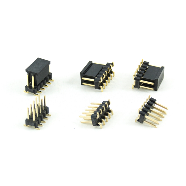
The Oupiin 2015-2X05G01DB is a double-row male pin header featuring ten positions arranged in two rows of five. It utilizes a 2.54mm (0.100 inch) pitch spacing for standard board-to-board or wire-to-board interconnections. The component supports termination via soldering directly to the printed circuit board. Electrical ratings indicate a current capacity ranging from 41.0 to 70.0 amps depending on specific contact configuration and environmental conditions. The connector type is classified as a standard box header designed for reliable signal and power transmission in embedded systems.
Verify that the requested part number matches the exact double-row, ten-position specification. Confirm RoHS compliance status if environmental regulations apply to your assembly process. Ensure the solder termination style aligns with your manufacturing equipment capabilities. Cross-reference the current rating requirements against your specific application load to guarantee adequate performance margins during operation.
Choose this component when a double-row arrangement is required to maximize connection density within a limited footprint. The 2.54mm pitch is suitable for standard through-hole mounting techniques. Consider the electrical current requirements carefully, as the rated range varies based on operational parameters. This header is appropriate for applications requiring robust mechanical stability alongside standard signal transmission needs.
This component belongs to the Oupiin 2015 series of headers, which typically includes various row counts and pin configurations. The 2X05 designation specifically indicates a double-row structure with five pins per side. Similar parts in this family may differ in pin count, such as single-row variants or different total position counts, while maintaining the same pitch and termination characteristics.
Direct substitutes must match the 2.54mm pitch, double-row format, and ten-pin count. Verify that alternative manufacturers offer identical mechanical dimensions and solder tail specifications. Ensure electrical ratings meet or exceed the original 41.0 to 70.0 amp range. Check for compatible housing materials and plating finishes to maintain interface reliability.
 2015-2X05G01DB
The activity of extra discounts on wholesale prices is in full swing…
Please fill in your contact information and we will send you the latest wholesale price list.