 ChipApex | Global Electronic Components Supplier
SEARCH
Search Product
Search Post
— IC芯片 | 连接器 | 传感器 | 被动器件 —
Search productSearch post
— IC芯片 | 连接器 | 传感器 | 被动器件 —
Consult the customer manager about the wholesale price.
consultation hotline:86-132-6715-2157
email:[email protected]
Contact the product manager for consultation. One-stop consultation is available.
Do you want a lower wholesale price? Please send us your inquiry and we will reply immediately.
The Microchip Technology 25LC160/P is a 16 Kbit (2048 x 8-bit) Serial Electrically Erasable PROM. It utilizes an SPI-compatible serial bus with SCK, SI, SO, and CS signals for communication. The device operates within a voltage range of 2.5 V to 5.5 V and supports a maximum clock frequency of 2 MHz. It features self-timed erase and write cycles with a maximum cycle time of 5 ms. The component is housed in an 8-pin PDIP package and supports industrial temperature ranges.
Verify the specific suffix 'P' corresponds to the 8-lead Plastic DIP package. Confirm the operating voltage range matches the system requirements of 2.5 V to 5.5 V. Check for any export restrictions or additional documentation required for procurement. Ensure the component meets the necessary environmental standards for the intended application environment.
Select this part for designs requiring low-power CMOS technology and simple serial interface compatibility. Consider the 2 MHz maximum clock speed and 5 ms write cycle time for timing constraints. Evaluate the need for hardware write protection via the WP pin versus software-based protection mechanisms. Verify that the 8-pin PDIP package fits the available board space and assembly process.
This component belongs to the 25XX160 family of 16 Kbit Serial EEPROMs from Microchip Technology. It is designed for direct interface with popular microcontroller families. The datasheet indicates it is not recommended for new designs, suggesting consideration of newer alternatives like the 25AA160A/B or 25LC160A/B series for future projects.
Public confirmed substitute part numbers: 25LC160A-E/P, 25LC160D-H/SN, 25LC160C-E/P.
The HOLD pin suspends transmission when pulled low while SCK is low, pausing communication without resetting the sequence. Transitions on SI, SCK, and SO are ignored during this state.
The WP pin prohibits writes to nonvolatile bits in the Status register when low and WPEN is high. When high, all functions operate normally. Its function can be blocked by clearing the WPEN bit.
The latch must be set via the WREN instruction before any write operation. It resets automatically upon power-up, successful execution of WRDI, WRSR, or WRITE instructions.
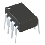 25LC160/P
The activity of extra discounts on wholesale prices is in full swing…
Please fill in your contact information and we will send you the latest wholesale price list.





