 ChipApex | Global Electronic Components Supplier

SEARCH
Search Product
Search Post
— IC芯片 | 连接器 | 传感器 | 被动器件 —
Search productSearch post
— IC芯片 | 连接器 | 传感器 | 被动器件 —
Consult the customer manager about the wholesale price.
consultation hotline:86-132-6715-2157
email:[email protected]
Contact the product manager for consultation. One-stop consultation is available.
Do you want a lower wholesale price? Please send us your inquiry and we will reply immediately.
The Microchip Technology 25LC256T-H/SN is a mid-density serial electrically erasable programmable read-only memory (EEPROM) with a storage capacity of 256 Kbit, organized as 32,768 x 8 bits. It operates within a supply voltage range of 2.5 V to 5.5 V and supports a maximum clock frequency of 5 MHz at voltages between 4.5 V and 5.5 V, or 3 MHz at 2.5 V to less than 4.5 V. The device utilizes an SPI-compatible interface and is housed in an 8-lead SOIC package. It features an extended temperature range from -40°C to +150°C.
Verify the specific suffix 'H' confirms the extended temperature grade (-40°C to +150°C) and 'SN' indicates the 8-lead SOIC package. Confirm the 'T' suffix denotes tape-and-reel packaging if required for automated assembly. Cross-reference the datasheet revision D specifications against current ordering guides to ensure compatibility with system voltage and timing requirements.
Select this component when designs require operation up to +150°C, exceeding standard industrial limits. Ensure the microcontroller SPI interface supports the required clock speeds for the target supply voltage. Verify that the page size of 64 bytes aligns with the application's write efficiency needs. Consider the block protection features if critical code or calibration data requires hardware-level safeguards against corruption.
This part belongs to the 25LCXXX family of mid-density serial EEPROMs manufactured by Microchip Technology. It shares architectural similarities with other densities in the series, such as the 25LC128 and 25LC640A, while differing in organization and page size. The device is designed for direct interfacing with SPI ports on popular microcontroller families.
The HOLD pin allows the user to pause transmission to the device without resetting the serial sequence. When pulled low while SCK is low, it places the SI, SCK, and SO pins in a high-impedance state. Communication resumes when HOLD is brought high while SCK is low.
Block protection is determined by the BP1 and BP0 bits in the STATUS register. These bits allow the user to protect none, the upper 1/4, the upper 1/2, or all of the memory array addresses.
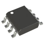 25LC256T-H/SN

The activity of extra discounts on wholesale prices is in full swing…
Please fill in your contact information and we will send you the latest wholesale price list.





