 ChipApex | Global Electronic Components Supplier

SEARCH
Search Product
Search Post
— IC芯片 | 连接器 | 传感器 | 被动器件 —
Search productSearch post
— IC芯片 | 连接器 | 传感器 | 被动器件 —
Consult the customer manager about the wholesale price.
consultation hotline:86-132-6715-2157
email:[email protected]
Contact the product manager for consultation. One-stop consultation is available.
Do you want a lower wholesale price? Please send us your inquiry and we will reply immediately.
The Microchip Technology 25LC320-E/SN is a 32 Kbit serial Electrically Erasable PROM featuring a 4096 x 8 bit organization. It operates within a voltage range of 2.5 V to 5.5 V and supports a maximum clock frequency of 2 MHz. The device utilizes an SPI-compatible interface with SCK, SI, SO, CS, HOLD, and WP pins. It offers high reliability with 1 million E/W cycles endurance and data retention exceeding 200 years. The component is housed in an 8-pin SOIC package and functions across an extended temperature range from -40 °C to +125 °C.
Verify the specific suffix 'E' indicates the automotive temperature grade (-40 °C to +125 °C) and 'SN' denotes the 8-pin SOIC package. Confirm the datasheet version matches the required specifications, as this device is not recommended for new designs; the 25LC320A series is the current recommendation. Ensure compatibility with the host SPI controller's voltage levels and timing requirements before procurement.
Select this component when an extended industrial or automotive temperature range is required alongside standard SPI EEPROM functionality. The 25LC320-E variant provides robustness for harsh environments compared to the standard industrial grade. Consider the 25LC320A series for new designs due to updated manufacturing processes and features while maintaining functional compatibility.
This part belongs to the 25XX320 family of 32 Kbit serial EEPROMs manufactured by Microchip Technology. The family includes variants like the 25AA320 and 25C320, differentiated primarily by supply voltage ranges and maximum clock frequencies. The 25LC320 specifically targets applications requiring 2.5 V to 5.5 V operation with 2 MHz speed capabilities.
The 25LC320A series is the recommended replacement for new designs. Verify pinout compatibility and electrical characteristics between the legacy 25LC320 and the newer A-series devices to ensure seamless integration without hardware modifications.
The HOLD pin suspends transmission to the device during a serial sequence without resetting the sequence. Transitions on SI, SCK, and SO are ignored while held low, allowing the host to service higher priority interrupts.
Write protection is configured via the Block Protection (BP1 and BP0) bits in the STATUS register. Users can protect none, the upper 1/4, the upper 1/2, or all of the memory array.
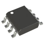 25LC320-E/SN

The activity of extra discounts on wholesale prices is in full swing…
Please fill in your contact information and we will send you the latest wholesale price list.





