 ChipApex | Global Electronic Components Supplier

SEARCH
Search Product
Search Post
— IC芯片 | 连接器 | 传感器 | 被动器件 —
Search productSearch post
— IC芯片 | 连接器 | 传感器 | 被动器件 —
Consult the customer manager about the wholesale price.
consultation hotline:86-132-6715-2157
email:[email protected]
Contact the product manager for consultation. One-stop consultation is available.
Do you want a lower wholesale price? Please send us your inquiry and we will reply immediately.
2N4392 PBFREE is listed in the Jfets range at ChipApex. The manufacturer field lists Central Semiconductor Corp. Its product description is JFET N-CH 40V TO18. Review the specifications below when checking this part for your BOM.
The Central Semiconductor Corp 2N4392 PBFREE is an N-channel silicon JFET housed in a TO-18 metal can package. Designed for analog switching and chopper applications, it features a maximum Gate-Drain Voltage of 40 V and Power Dissipation of 1.8 W at 25°C. The device operates within a junction temperature range of -65 to +175 °C. Key electrical parameters include an IDSS range of 25 to 75 mA at VDS=20V, and a VGS(OFF) range of 2.0 to 5.0 V. It exhibits low input leakage current (IGSS max 0.1 nA at 25°C) and specific on-resistance values depending on the drain current.
Verify the component matches the exact part number 2N4392 PBFREE when sourcing. Confirm that the ordering suffix PBFREE indicates lead-free plating as per manufacturer standards. Ensure the supplier provides the official datasheet R3 dated 18-August-2022 for accurate parameter validation before integration into designs.
Select this component when designing circuits requiring low leakage and defined pinch-off voltages between 2.0 V and 5.0 V. Compare IDSS ranges against circuit requirements to ensure proper biasing. Consider the TO-18 package constraints for thermal management and mechanical mounting in the final assembly layout.
This device belongs to the 2N4391 series family, which includes the 2N4391 and 2N4393 variants. These parts share identical maximum ratings and physical characteristics but differ in electrical thresholds such as IDSS and VGS(OFF). The 2N4392 offers intermediate performance specifications compared to its siblings within the same silicon JFET lineup.
Direct substitutes within the same family include the 2N4391 and 2N4393, provided their specific IDSS and VGS(OFF) ranges align with the design requirements. Verify pinout compatibility, as all variants use the standard Source-Drain-Gate configuration for the TO-18 case.
The maximum power dissipation is 1.8 W when the case temperature is maintained at 25°C.
Pin 1 is the Source, Pin 2 is the Drain, and Pin 3 is the Gate.
The reverse transfer capacitance is typically 4.0 pF or less, measured at VGS=7.0V, VDS=0, and f=1.0MHz.
Explore related parts through Transistors, Discrete Semiconductor Products, all product categories, ChipApex homepage.
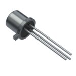 2N4392 PBFREE

The activity of extra discounts on wholesale prices is in full swing…
Please fill in your contact information and we will send you the latest wholesale price list.





