ChipApex | Global Electronic Components Supplier

SEARCH
Search Product
Search Post
— IC芯片 | 连接器 | 传感器 | 被动器件 —
Search productSearch post
— IC芯片 | 连接器 | 传感器 | 被动器件 —
Consult the customer manager about the wholesale price.
consultation hotline:86-132-6715-2157
email:[email protected]
Contact the product manager for consultation. One-stop consultation is available.
Do you want a lower wholesale price? Please send us your inquiry and we will reply immediately.
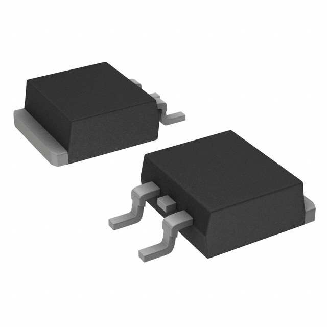
2SD12950RL is listed in the Single Bipolar Transistors range at ChipApex. The manufacturer field lists Panasonic Electronic Components. Its product description is TRANS NPN 40V 1.5A U-G2. Review the specifications below when checking this part for your BOM.
The Panasonic 2SD1295 is a silicon NPN epitaxial planar power transistor designed for low-frequency output amplification. It operates with a collector-emitter voltage of 40 V and a continuous collector current of 1.5 A, capable of handling peak currents up to 3 A. The device dissipates 10 W of power at 25°C and features a transition frequency of 150 MHz. It utilizes the U-G2 (SC-63) package, allowing direct soldering of the radiation fin to printed circuit boards.
Verify the specific ordering suffix against official documentation to confirm exact packaging and compliance status. Confirm the current lifecycle stage, as this component may be subject to planned maintenance or discontinuation. Ensure that the final specifications align with the most recent product standards before purchasing.
Select this component for low-frequency power amplification tasks requiring high thermal dissipation capabilities. The U-G2 package facilitates efficient heat transfer through direct board mounting. Consider pairing with the complementary 2SB0968 for push-pull configurations to maximize output power within the specified voltage and current limits.
This component belongs to the Panasonic 2SD series of silicon NPN transistors. It is specifically engineered for general-purpose power amplification where robust thermal management is required. The design supports standard industrial and consumer electronics manufacturing processes.
The datasheet identifies the 2SB0968 as the complementary pair for this device. No other direct replacement part numbers are documented in the provided source material.
The maximum collector power dissipation is 10 W at a case temperature of 25°C.
Yes, the U-G2 package allows the radiation fin to be soldered directly to the printed circuit board.
The forward current transfer ratio (hFE) ranges from 80 to 220 under specified test conditions.
Explore related parts through Bipolar (BJT), Transistors, Discrete Semiconductor Products, all product categories.
 2SD12950RL

The activity of extra discounts on wholesale prices is in full swing…
Please fill in your contact information and we will send you the latest wholesale price list.