ChipApex | Global Electronic Components Supplier
SEARCH
Search Product
Search Post
— IC芯片 | 连接器 | 传感器 | 被动器件 —
Search productSearch post
— IC芯片 | 连接器 | 传感器 | 被动器件 —
Consult the customer manager about the wholesale price.
consultation hotline:86-132-6715-2157
email:[email protected]
Contact the product manager for consultation. One-stop consultation is available.
Do you want a lower wholesale price? Please send us your inquiry and we will reply immediately.
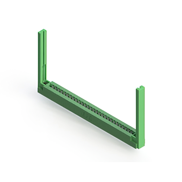
The EDAC Inc. part number 306-028-420-168 is a dual-edge card edge connector designed for high-density interconnect applications. It features 56 positions arranged in a double-row configuration with a contact spacing of 0.156 inches (3.96 mm). The connector utilizes female contacts with a tin plating finish to ensure reliable signal transmission. Constructed with a green insulator, it supports PCB thicknesses ranging from 0.051 to 0.071 inches. The component operates within a temperature range of -55°C to +85°C and meets RoHS3 standards for environmental compliance.
Verify the specific ordering suffix against the manufacturer's current datasheet to confirm terminal type and plating specifications. Ensure the target PCB thickness falls within the supported range of 0.051 to 0.071 inches for proper mechanical engagement. Confirm that the application environment remains within the specified operating temperature limits of -55°C to +85°C. Cross-reference the pin count and row configuration with the schematic requirements before finalizing procurement orders.
Select this connector when a dual-edge interface with 0.156-inch spacing is required for robust signal integrity. The tin-plated contacts offer a cost-effective solution compared to gold plating while maintaining durability. Consider the green insulator color for visual identification during assembly processes. Evaluate the flush mount style against available panel clearance constraints. This series provides a standardized footprint compatible with various industrial form factors.
This component belongs to the EDAC 306 Series, which specializes in standard card edge connectors. The series offers various position counts and spacing options to accommodate diverse board layouts. EDAC designs these connectors to meet rigorous industrial standards for reliability. The 306 line emphasizes durable construction suitable for repeated mating cycles in demanding environments.
Consult official cross-reference guides for equivalent dual-edge connectors with matching 0.156-inch spacing and 56-position configurations. Verify that substitute parts maintain identical PCB thickness tolerances and mounting styles. Ensure replacement components support the same electrical ratings and environmental operating ranges.
 306-028-420-168
The activity of extra discounts on wholesale prices is in full swing…
Please fill in your contact information and we will send you the latest wholesale price list.