 ChipApex | Global Electronic Components Supplier

SEARCH
Search Product
Search Post
— IC芯片 | 连接器 | 传感器 | 被动器件 —
Search productSearch post
— IC芯片 | 连接器 | 传感器 | 被动器件 —
Consult the customer manager about the wholesale price.
consultation hotline:86-132-6715-2157
email:[email protected]
Contact the product manager for consultation. One-stop consultation is available.
Do you want a lower wholesale price? Please send us your inquiry and we will reply immediately.
74ALVC16834ADGG:11 is listed in the Buffers, Drivers, Receivers, Transceivers range at ChipApex. The manufacturer field lists Nexperia USA Inc.. Its product description is IC BUF NON-INVERT 3.6V 56TSSOP. Review the specifications below when checking this part for your BOM.
The Nexperia 74ALVC16834ADGG,11 is an 18-bit registered driver with inverted register enable and 3-state outputs. It operates within a supply voltage range of 1.2 V to 3.6 V. The device features low-power CMOS consumption and direct interface capability with TTL levels when operating between 2.7 V and 3.6 V. It provides a current drive of ±24 mA at VCC = 3.0 V and supports output drive for 50 Ω transmission lines at 85°C. Propagation delay ranges from 1.0 ns to 4.2 ns depending on voltage. It utilizes a TSSOP56 package (SOT364-1) and functions across an ambient temperature range of -40 °C to +85 °C.
Verify the specific ordering suffix
Select this component for designs requiring 18-bit parallel data registration with minimal propagation delay. Ensure the application environment stays within the specified -40 °C to +85 °C temperature range. Confirm that the system power supply remains stable between 1.2 V and 3.6 V to maintain optimal performance and adhere to JEDEC standards.
This part belongs to the 74ALVC family of high-speed CMOS logic devices manufactured by Nexperia. It is specifically engineered for applications demanding fast switching speeds and low power dissipation. The ALVC series is widely used in portable and battery-operated systems due to its wide voltage compatibility and efficient power characteristics.
Check for direct substitutes such as the 74ALVC16834ADGGY if availability is required. Verify pinout compatibility and electrical specifications before swapping components.
When LE is LOW, the A to Y data flow is transparent. When LE is HIGH and the clock (CP) is held steady, data is latched; data is stored in the flip-flop on the LOW to HIGH transient of CP.
To ensure a high-impedance state during power up or power down, the OE input should be tied to VCC through a pull-up resistor. The minimum resistor value is determined by the current-sinking capability of the driver.
Explore related parts through Logic, Integrated Circuits (ICs), all product categories, ChipApex homepage.
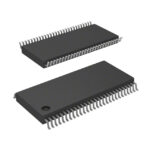 74ALVC16834ADGG:11

The activity of extra discounts on wholesale prices is in full swing…
Please fill in your contact information and we will send you the latest wholesale price list.





