 ChipApex | Global Electronic Components Supplier
SEARCH
Search Product
Search Post
— IC芯片 | 连接器 | 传感器 | 被动器件 —
Search productSearch post
— IC芯片 | 连接器 | 传感器 | 被动器件 —
Consult the customer manager about the wholesale price.
consultation hotline:86-132-6715-2157
email:[email protected]
Contact the product manager for consultation. One-stop consultation is available.
Do you want a lower wholesale price? Please send us your inquiry and we will reply immediately.
The onsemi 74F579PC is an 8-bit bidirectional binary counter featuring multiplexed 3-STATE I/O ports for bus-oriented applications. It supports parallel loading and carry lookahead for cascading. The device operates within a supply voltage range of +4.5V to +5.5V and functions at temperatures from 0°C to +70°C. Key electrical parameters include a typical count frequency of 100 MHz, maximum clock frequency of 80 MHz, and propagation delays ranging from 3.0 ns to 13.5 ns depending on the signal path. Supply current typically ranges from 70 mA to 120 mA.
Verify component authenticity through official manufacturer channels or authorized distributors. Confirm package type matches the N20A designation for 20-Lead Plastic Dual-In-Line Package. Review datasheet specifications for absolute maximum ratings to ensure operational safety. Check for RoHS compliance documentation if required by project standards.
Select this component for designs requiring high-speed bidirectional counting with integrated bus interface capabilities. Ensure power supply stability within the 4.5V to 5.5V range to maintain specified timing characteristics. Consider thermal management due to typical supply currents exceeding 70 mA. Verify that the 3-STATE output impedance meets system bus requirements.
This part belongs to the 74F logic family, known for high-speed performance in standard TTL-compatible applications. The 74F579 specifically addresses needs for complex counting operations with flexible input/output configurations. It serves as a specialized solution for digital systems requiring precise synchronization and direction control.
Direct substitutes may include other 8-bit bidirectional counters with 3-STATE outputs from compatible logic families. Verify pin compatibility and electrical characteristics before substitution. Consult manufacturer cross-reference guides for equivalent parts with similar functionality and package dimensions.
The U/D (Up/Down) input determines the counting direction. A HIGH level enables up-counting, while a LOW level enables down-counting.
Parallel data is loaded when both PE (Parallel Enable) and CS (Chip Select) inputs are LOW, triggered by the rising edge of the clock pulse.
The TC (Terminal Count) output indicates when the counter reaches its terminal value. It goes LOW when the count limit is reached, useful for cascading multiple counters.
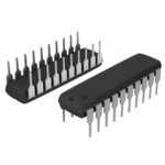 74F579PC
The activity of extra discounts on wholesale prices is in full swing…
Please fill in your contact information and we will send you the latest wholesale price list.





