 ChipApex | Global Electronic Components Supplier

SEARCH
Search Product
Search Post
— IC芯片 | 连接器 | 传感器 | 被动器件 —
Search productSearch post
— IC芯片 | 连接器 | 传感器 | 被动器件 —
Consult the customer manager about the wholesale price.
consultation hotline:86-132-6715-2157
email:[email protected]
Contact the product manager for consultation. One-stop consultation is available.
Do you want a lower wholesale price? Please send us your inquiry and we will reply immediately.
74HCT9114D,118 is listed in the Inverter Gates range at ChipApex. The manufacturer field lists Nexperia USA Inc.. Its product description is IC INVERT SCHMITT 9CH 1-INP 20SO. Review the specifications below when checking this part for your BOM.
The Nexperia 74HCT9114D,118 is a nine-wide Schmitt trigger buffer with open drain outputs and inverting logic. It operates within a supply voltage range of 4.5 V to 5.5 V and supports an ambient temperature range from -40 °C to +125 °C. The device features TTL input levels and includes clamp diodes on inputs for overvoltage interfacing. Static characteristics specify a maximum supply current of 160 μA at 5.5 V. Dynamic performance indicates a typical propagation delay of 31 ns at 4.5 V and 13 ns at 5.0 V with a 15 pF load.
Verify the specific ordering code 74HCT9114D,118 against the manufacturer's latest datasheet revision history to ensure compliance with current JEDEC standards and ESD protection specifications. Confirm package details match SOT163-1 (SO20) requirements for your PCB layout.
Select this component when nine independent inverting channels with hysteresis are required. The HCT logic family ensures compatibility with standard TTL voltage levels while maintaining CMOS power efficiency. Ensure the application can accommodate open drain output limitations regarding pull-up resistor selection.
This part belongs to the 74HCT series of high-speed CMOS logic devices manufactured by Nexperia. It provides a wide buffer solution compared to single-channel inverters, consolidating multiple logic functions into a single SO20 package to reduce board space.
The 74HC9114D variant serves as a logical alternative if CMOS input thresholds are preferred over TTL levels, though electrical parameters differ.
The open drain outputs require an external pull-up resistor connected to a voltage source to drive the output HIGH. They cannot actively source current.
The clamp diodes protect the internal circuitry by conducting excess current when input voltages exceed the supply voltage, provided a current-limiting resistor is used.
Explore related parts through Logic, Integrated Circuits (ICs), all product categories, ChipApex homepage.
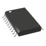 74HCT9114D,118

The activity of extra discounts on wholesale prices is in full swing…
Please fill in your contact information and we will send you the latest wholesale price list.





