 ChipApex | Global Electronic Components Supplier

SEARCH
Search Product
Search Post
— IC芯片 | 连接器 | 传感器 | 被动器件 —
Search productSearch post
— IC芯片 | 连接器 | 传感器 | 被动器件 —
Consult the customer manager about the wholesale price.
consultation hotline:86-132-6715-2157
email:[email protected]
Contact the product manager for consultation. One-stop consultation is available.
Do you want a lower wholesale price? Please send us your inquiry and we will reply immediately.
74LVC14AS14-13 is listed in the Inverter Gates range at ChipApex. The manufacturer field lists Diodes Incorporated. Its product description is IC INVERT SCHMITT 6CH 1-INP 14SO. Review the specifications below when checking this part for your BOM.
The Diodes Incorporated 74LVC14AS14-13 is a hex inverter with Schmitt trigger inputs, part of the LVC logic family. It operates within a supply voltage range of 1.65V to 5.5V and features outputs capable of sinking or sourcing 24mA at VCC = 3.3V. The device includes IOFF circuitry for partial power-down applications, preventing damaging current backflow. Inputs are tolerant to 5.5V, facilitating mixed-voltage environments. It is available in SO-14 and TSSOP-14 packages.
Verify the specific package suffix (S14 for SO-14 or T14 for TSSOP-14) against your PCB footprint requirements. Confirm that the -13 tape and reel packing quantity aligns with your manufacturing line setup. Ensure input voltage levels do not exceed the absolute maximum ratings during transient conditions.
Select this component when noise immunity is required due to its Schmitt trigger input characteristics. It is suitable for designs needing robust signal restoration from slow-rising waveforms. Consider the 24mA drive capability if driving moderate capacitive loads directly without additional buffering stages.
This part belongs to the 74LVC14A series of hex inverters with Schmitt triggers manufactured by Diodes Incorporated. The 'S14' suffix indicates the SO-14 surface mount package variant. It is designed for low-voltage digital applications requiring high noise immunity and flexible voltage translation capabilities across various consumer and industrial electronics.
Compatible substitutes include other manufacturers' 74LVC14 devices in equivalent packages. Verify pinout compatibility and electrical specifications such as propagation delay and output drive strength before substitution.
The IOFF circuitry disables the outputs when the device is powered down, preventing damaging current backflow from powered rails into unpowered pins.
Yes, the inputs are tolerant to 5.5V, allowing them to accept signals from 3.3V or 5.5V sources even if the device itself is powered at lower voltages.
Explore related parts through Logic, Integrated Circuits (ICs), all product categories, ChipApex homepage.
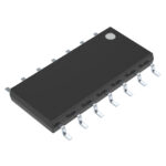 74LVC14AS14-13

The activity of extra discounts on wholesale prices is in full swing…
Please fill in your contact information and we will send you the latest wholesale price list.





