 ChipApex | Global Electronic Components Supplier
SEARCH
Search Product
Search Post
— IC芯片 | 连接器 | 传感器 | 被动器件 —
Search productSearch post
— IC芯片 | 连接器 | 传感器 | 被动器件 —
Consult the customer manager about the wholesale price.
consultation hotline:86-132-6715-2157
email:[email protected]
Contact the product manager for consultation. One-stop consultation is available.
Do you want a lower wholesale price? Please send us your inquiry and we will reply immediately.
The A5366CA-T is a low-current BiCMOS integrated circuit designed for photoelectric smoke detectors. It interfaces with an infrared chamber to detect scattered light from smoke particles and supports interconnecting up to 50 units for synchronized alarms. The device operates on a 6 V to 12 V supply, drawing an average standby current of 9 μA. It features a variable-gain photoamplifier, internal timing circuits, and a piezoelectric horn driver. The component is housed in a 16-pin DIP package (suffix A) with lead-free matte-tin plating (suffix –T). It is rated for continuous operation between –25°C and 75°C.
Verify the specific ordering suffix to confirm the package type and lead finish. The CA-T designation indicates a 16-pin through-hole DIP package with lead-free matte-tin plating. Confirm that the procurement channel provides the official datasheet and ensures compliance with the specified operating temperature range of –25°C to 75°C for the intended application environment.
Select this component when designing a photoelectric smoke detector requiring networked alarm capabilities and low standby power consumption. Ensure the external circuitry accommodates the 6 V to 12 V supply range and includes necessary components for the variable-gain photoamplifier. Verify that the application utilizes a 16-pin DIP footprint compatible with the Package A dimensions provided in the datasheet.
The A5366CA-T belongs to the A5366 series of smoke detector ICs manufactured by Allegro MicroSystems. This series provides specialized solutions for both ionization and photoelectric smoke detection technologies. The A5366 specifically addresses photoelectric applications with integrated timer and interconnect functions, distinguishing it from other sensor or driver families within the manufacturer's portfolio.
The A5366CLWTR-T serves as a surface-mount alternative within the same family, utilizing a 16-pin SOICW package instead of the DIP configuration. Designers transitioning from DIP to surface mount must account for differences in thermal resistance and PCB layout requirements while maintaining functional compatibility.
During a local alarm, the internal gain of the photoamplifier increases by approximately 10% to reduce false triggering. Additionally, the I/O input requires three consecutive high samples plus one additional cycle to trigger an alarm from a remote unit, providing significant immunity to noise.
The HUSH pin enables or disables the internal 10-minute 'hush' timer mode. When the voltage exceeds 1.5 V, timer mode is enabled, allowing reduced sensitivity to nuisance alarms. If connected to VSS or left open with less than 0.5 V, timer mode is disabled.
This mode is initiated by pulling the TEST pin below VSS by continuously drawing 400 μA from the pin for at least one clock cycle on OSC CAP. In this mode, certain pins are reconfigured to facilitate calibration of the IC and assembled detector.
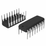 A5366CA-T
The activity of extra discounts on wholesale prices is in full swing…
Please fill in your contact information and we will send you the latest wholesale price list.





