 ChipApex | Global Electronic Components Supplier

SEARCH
Search Product
Search Post
— IC芯片 | 连接器 | 传感器 | 被动器件 —
Search productSearch post
— IC芯片 | 连接器 | 传感器 | 被动器件 —
Consult the customer manager about the wholesale price.
consultation hotline:86-132-6715-2157
email:[email protected]
Contact the product manager for consultation. One-stop consultation is available.
Do you want a lower wholesale price? Please send us your inquiry and we will reply immediately.
The A54SX08A-1PQ208 is a nonvolatile Field Programmable Gate Array from the SX-A family, fabricated using 0.22 μm / 0.25 μm CMOS antifuse technology. It provides 12,000 system gates and 768 logic modules (comprising 512 combinatorial cells and 256 dedicated flip-flops). The device supports up to 130 user-programmable I/O pins within a 208-pin Plastic Quad Flat Pack (PQFP) package. It operates at a maximum system frequency of 250 MHz with internal performance reaching 350 MHz. Electrical specifications include a supply voltage range of 2.25 V to 5.25 V for both core and I/O domains, supporting mixed-voltage operation with 5 V input tolerance.
Verify the specific ordering suffix 'I' corresponds to the Industrial temperature grade (-40°C to +85°C) as defined in the manufacturer's matrix. Confirm that the package type PQFP matches the required footprint dimensions. Ensure compatibility with the Actel Designer software version used for programming the antifuse structure.
Select this component when a single-chip nonvolatile solution is required to replace multiple CPLDs or FPGAs. Consider the 250 MHz speed grade if deterministic timing and high performance are critical. Evaluate the 130 I/O count against interface requirements before choosing larger capacity devices in the SX-A family.
This part belongs to the Microsemi (formerly Actel) SX-A family of FPGAs. It utilizes metal-to-metal programmable antifuse interconnect elements for permanent configuration. The architecture features a sea-of-modules design with specialized routing resources to optimize silicon utilization and signal propagation delays.
Compatible variants within the same package include A54SX08A-2PQ208I for higher speed grades. Cross-family replacements may require architectural re-evaluation due to differences in configuration memory types and routing structures.
Unused I/Os are configured as tristate outputs by the Actel Designer software to provide maximum flexibility during board design.
No, the HCLK pin must not be left floating. If not used, it must be set to Low or High on the board to prevent false output levels.
The device is power-up/down friendly, requiring no sequencing for supply voltages. All I/Os are tristated during power-up until normal operating conditions are reached.
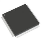 A54SX08A-1PQ208

The activity of extra discounts on wholesale prices is in full swing…
Please fill in your contact information and we will send you the latest wholesale price list.





