 ChipApex | Global Electronic Components Supplier
SEARCH
Search Product
Search Post
— IC芯片 | 连接器 | 传感器 | 被动器件 —
Search productSearch post
— IC芯片 | 连接器 | 传感器 | 被动器件 —
Consult the customer manager about the wholesale price.
consultation hotline:86-132-6715-2157
email:[email protected]
Contact the product manager for consultation. One-stop consultation is available.
Do you want a lower wholesale price? Please send us your inquiry and we will reply immediately.
The STMicroelectronics ACS302-5T3 is a three-line AC switch array built on the ASD™ concept, designed for static switching in appliance and industrial control systems. It integrates three bidirectional AC switches capable of controlling resistive or inductive loads up to 0.2 A per line, with a total nominal conducting current of 0.4 A for the array. The device features a repetitive peak off-state voltage (VDRM/VRRM) of 500 V and a clamping voltage (VCL) of 600 V. Gate triggering requires a negative current with IGT less than 5 mA. Packaged in an SO-20 wired configuration, it interfaces directly with microcontrollers while eliminating gate kickback stress.
Verify component authenticity through authorized distributors or direct manufacturer channels. Confirm package integrity and pin alignment against the SO-20 outline specifications. Check manufacturing date codes and lot traceability records to ensure compliance with RoHS3 directives. Review datasheet revisions for any updates to electrical characteristics or thermal resistance values prior to final procurement validation.
Select this component when designing circuits requiring isolated control of multiple low-power AC loads from a single microcontroller interface. Ensure the load current does not exceed 0.2 A per channel or 0.4 A total RMS under specified ambient temperatures. Verify that the system can accommodate the negative gate trigger current requirement and that the PCB layout supports the SO-20 thermal dissipation needs for continuous operation.
The ACS302-5T3 belongs to STMicroelectronics' AC line switch family utilizing the ASD™ technology. It serves as a specialized integrated solution for replacing discrete triac and protection networks in household appliances. The device consolidates switching, clamping, and isolation functions into a single surface-mount package, reducing bill-of-materials complexity and assembly footprint in multi-channel AC control applications.
Public confirmed substitute part numbers: ACS102-6T1-TR
Each switch is triggered by a negative gate current flowing out of the gate pin, allowing direct interfacing with digital controllers through a resistor.
The internal avalanche diode conducts the stored inductive energy, limiting the voltage across the switch to the clamping voltage (VCL) until the current reaches zero.
No, the device includes built-in high-voltage clamping structures that absorb inductive turn-off energy and withstand AC line transients up to 2 kV according to IEC61000-4-5 standards.
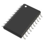 ACS302-5T3-TR
The activity of extra discounts on wholesale prices is in full swing…
Please fill in your contact information and we will send you the latest wholesale price list.





