 ChipApex | Global Electronic Components Supplier
SEARCH
Search Product
Search Post
— IC芯片 | 连接器 | 传感器 | 被动器件 —
Search productSearch post
— IC芯片 | 连接器 | 传感器 | 被动器件 —
Consult the customer manager about the wholesale price.
consultation hotline:86-132-6715-2157
email:[email protected]
Contact the product manager for consultation. One-stop consultation is available.
Do you want a lower wholesale price? Please send us your inquiry and we will reply immediately.
The AD2S1210ASTZ is a monolithic resolver-to-digital converter (RDC) from Analog Devices, packaged in a 48-lead LQFP. It provides variable resolution from 10-bit to 16-bit and integrates an on-board programmable sinusoidal oscillator for resolver excitation. The device accepts differential sine/cosine input signals with amplitudes between 2.3 V p-p and 4.0 V p-p at frequencies of 2 kHz to 20 kHz. It features a Type II tracking loop for continuous position data output without conversion delay. The component operates on a single 5 V supply with logic interface voltages ranging from 2.3 V to 5.25 V, supporting both parallel and serial digital interfaces.
Verify the specific grade suffix 'A' against the manufacturer's ordering guide to confirm the operational temperature range and accuracy specifications. Ensure that the required resolution setting aligns with the supported frequency ranges defined in the datasheet specifications table.
Select this component when a complete RDC solution with integrated excitation is required. Confirm that the application's clock input frequency falls within the 6.144 MHz to 10.24 MHz range. Verify that the resolver input signal amplitude remains within the 2.3 V p-p to 4.0 V p-p limits to ensure proper operation of the Type II tracking loop.
The AD2S1210ASTZ belongs to the AD2S1210 family of high-performance resolver-to-digital converters. This series is designed for applications requiring precise angular position and velocity feedback. The ASTZ variant specifically denotes the A-grade version of the device, which typically offers standard industrial performance characteristics compared to higher precision B or D grades.
Consult the official Analog Devices ordering guide for direct pin-compatible alternatives such as the AD2S1210BSTZ or AD2S1210CDSTZ. Substitution requires verification of the operating temperature range and angular accuracy specifications to ensure compatibility with the existing design requirements.
The maximum tracking rate is 3125 rps when operating at 10-bit resolution with a clock input frequency of 10.24 MHz.
Resolution is user-selectable between 10, 12, 14, and 16 bits by configuring the RES0 and RES1 logic inputs.
The sine and cosine inputs accept differential sinusoidal waveforms with voltage amplitudes ranging from 2.3 V p-p to 4.0 V p-p.
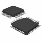 AD2S1210ASTZ
The activity of extra discounts on wholesale prices is in full swing…
Please fill in your contact information and we will send you the latest wholesale price list.





