 ChipApex | Global Electronic Components Supplier
SEARCH
Search Product
Search Post
— IC芯片 | 连接器 | 传感器 | 被动器件 —
Search productSearch post
— IC芯片 | 连接器 | 传感器 | 被动器件 —
Consult the customer manager about the wholesale price.
consultation hotline:86-132-6715-2157
email:[email protected]
Contact the product manager for consultation. One-stop consultation is available.
Do you want a lower wholesale price? Please send us your inquiry and we will reply immediately.
The AD5116BCPZ5-RL7 is a single-channel, nonvolatile digital potentiometer featuring 64 adjustment positions and a push-button interface. It offers ±8% nominal resistor tolerance with wiper currents up to ±6 mA for the 5 kΩ and 10 kΩ variants. Operating on a 2.3 V to 5.5 V supply, it consumes a maximum of 2.5 µA at 2.7 V. The device includes built-in EEPROM for data retention, ensuring the last wiper position is restored within 50 µs of power-up. It supports rheostat and potentiometer modes, providing bandwidths up to 4 MHz for the 5 kΩ option.
Verify the specific resistance value suffix in the full part number, as the AD5116 family is available in 5 kΩ, 10 kΩ, and 80 kΩ options. Confirm the package type matches the required footprint, typically an 8-lead LFCSP. Ensure the ordering suffix corresponds to the correct tape and reel quantity specified by the manufacturer for the RL7 designation.
Select based on required end-to-end resistance (5 kΩ, 10 kΩ, or 80 kΩ) which dictates current limits and bandwidth. The 5 kΩ version offers the highest bandwidth (4 MHz), while the 80 kΩ version has lower current capability (±1.5 mA). Verify that the application voltage range falls within the 2.3 V to 5.5 V specification and that the operating temperature stays within −40°C to +125°C.
The AD5116 belongs to Analog Devices' NVM ±8% Resistor Tolerance family, designed as a direct replacement for mechanical potentiometers. It distinguishes itself from I2C-controlled models (like AD5110/AD5112) by using a simple two-push-button interface (PU/PD) for user-adjustable settings without requiring a microcontroller for basic operation.
Direct functional replacements within the same family include AD5110, AD5111, AD5112, AD5113, AD5114, and AD5115. Note that these alternatives may differ in interface type (I2C vs. Push Button) or resolution (32 vs. 64 positions). Ensure the substitute matches the required resistance value and package dimensions.
It features a built-in adaptive debouncer that ignores invalid bounces. A logic high signal must last longer than 8 ms to be recognized as a valid increment or decrement command.
The device includes extra steps to minimize wiper resistance. At bottom scale (RBS), the typical resistance is 45 Ω, and at top scale (RTS), it is typically 70 Ω.
Yes, while the supply (VDD to GND) must be positive, the voltage across terminals A, B, and W can have no polarity limitations relative to each other, provided they remain within the GND to VDD range.
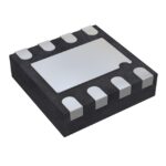 AD5116BCPZ5-RL7
The activity of extra discounts on wholesale prices is in full swing…
Please fill in your contact information and we will send you the latest wholesale price list.




