 ChipApex | Global Electronic Components Supplier

SEARCH
Search Product
Search Post
— IC芯片 | 连接器 | 传感器 | 被动器件 —
Search productSearch post
— IC芯片 | 连接器 | 传感器 | 被动器件 —
Consult the customer manager about the wholesale price.
consultation hotline:86-132-6715-2157
email:[email protected]
Contact the product manager for consultation. One-stop consultation is available.
Do you want a lower wholesale price? Please send us your inquiry and we will reply immediately.
AD5222BRZ10 is listed in the Digital Potentiometers range at ChipApex. The manufacturer field lists Analog Devices Inc.. Its product description is IC DGTL POT 10KOHM 128TAP 14SOIC. Review the specifications below when checking this part for your BOM.
The AD5222BRZ10 is a dual-channel, 7-bit (128-position) digitally controlled variable resistor with a nominal end-to-end resistance of 10 kΩ. It operates on a single supply from 2.7 V to 5.5 V or a dual supply of ±2.3 V to ±2.7 V. The device features an increment/decrement interface using CS, CLK, and U/D inputs, eliminating the need for microcontrollers in push-button applications. Key electrical parameters include a maximum supply current of 40 µA, a wiper resistance of 45 Ω to 100 Ω, and a temperature coefficient of –35 ppm/°C. It is housed in a 14-lead SOIC package.
Verify the specific suffix 'BRZ' corresponds to the SOIC-14 package and lead-free status as defined in the manufacturer's ordering guide. Confirm that the '10' designation matches the required 10 kΩ resistance value. Ensure compatibility with the -40°C to +85°C industrial temperature range specified for this variant.
Select this component when a dual-channel digital potentiometer with simple up/down control is required instead of SPI interfaces. The 10 kΩ resistance offers a balance between bandwidth (1 MHz typical) and power dissipation. Consider the volatile memory nature, which requires re-initialization upon power loss, unlike non-volatile variants.
The AD5222 series includes variants with 10 kΩ, 50 kΩ, 100 kΩ, and 1 MΩ resistances. The BRZ suffix indicates a RoHS-compliant SOIC-14 package, while BRU denotes a TSSOP-14 option. All variants share the same 128-position resolution and digital interface functionality.
Direct pin-compatible replacements within the same family include AD5222BRZ50 (50 kΩ), AD5222BRZ100 (100 kΩ), and AD5222BRZ1M (1 MΩ). For different packages, AD5222BRU10 provides the same electrical characteristics in a TSSOP-14 footprint.
Upon power-up, the internal power-on reset (POR) circuitry automatically sets both wipers to a centered position, providing nearly equal resistance values to terminals A and B.
In Common Mode (MODE = 0), both wipers increment or decrement together, preserving their relative distance. In Independent Mode (MODE = 1), only the wiper selected by the DACSEL pin changes position.
Yes, the increment/decrement interface is designed for direct connection to mechanical or push-button switches, though external debounce circuitry is recommended to ensure clean clock signals.
Explore related parts through Data Acquisition, Integrated Circuits (ICs), all product categories, ChipApex homepage.
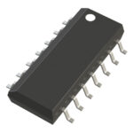 AD5222BRZ10

The activity of extra discounts on wholesale prices is in full swing…
Please fill in your contact information and we will send you the latest wholesale price list.





