 ChipApex | Global Electronic Components Supplier
SEARCH
Search Product
Search Post
— IC芯片 | 连接器 | 传感器 | 被动器件 —
Search productSearch post
— IC芯片 | 连接器 | 传感器 | 被动器件 —
Consult the customer manager about the wholesale price.
consultation hotline:86-132-6715-2157
email:[email protected]
Contact the product manager for consultation. One-stop consultation is available.
Do you want a lower wholesale price? Please send us your inquiry and we will reply immediately.
The AD807A-155BRZRL7 is a fiber optic receiver with quantizer, clock recovery, and data retiming capabilities. It operates at a nominal center frequency of 155.52 MHz with a capture range of 155 to 156 MHz. The device accepts NRZ data without preamble requirements and features a quantizer sensitivity of 2 mV. Power supply voltage ranges from 4.5 V to 5.5 V, drawing a typical current of 34.5 mA. Output jitter is specified at 2.0 degrees RMS.
Verify the specific ordering suffix RL7 corresponds to the 7-inch reel packaging configuration as defined in the Analog Devices ordering guide. Confirm that the AD807A-155BRZRL7 variant meets the required -40°C to +85°C industrial temperature range specifications. Ensure compatibility with the 16-lead narrow SOIC package dimensions for PCB layout integration.
Select this component when designing high-integration, low-power fiber optic receivers for 155 Mbps applications. It is suitable for designs requiring crystal-less clock recovery and adjustable signal level detection. Consider the single-supply operation and ECL/PECL compatible outputs for interface compatibility with downstream digital logic circuits.
The AD807A-155BRZRL7 belongs to the AD807 family of integrated circuit receivers manufactured by Analog Devices. This series is designed specifically for optical communication networks operating at 155 Mbps. The device combines analog front-end processing with digital retiming functions into a single monolithic silicon chip.
The AD807A-155BR is the non-reel equivalent within the same product family. Both variants share identical electrical characteristics and functionality, differing only in the shipping packaging format. Verify pinout and thermal requirements remain consistent when substituting between reel and tube configurations.
No, the AD807 uses a Phase-Locked Loop with a frequency acquisition control loop that acquires lock on random or scrambled data without requiring an external crystal or SAW filter.
The user sets these parameters by choosing a damping factor capacitor connected between pins CF1 and CF2. A larger capacitance increases damping and reduces peaking but may increase acquisition time.
The SDOUT pin provides a Signal Detect Output that indicates when the input signal level has fallen below a user-adjustable threshold, signaling a Loss of Signal (LOS) event.
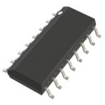 AD807A-155BRZRL7
The activity of extra discounts on wholesale prices is in full swing…
Please fill in your contact information and we will send you the latest wholesale price list.






