 ChipApex | Global Electronic Components Supplier
SEARCH
Search Product
Search Post
— IC芯片 | 连接器 | 传感器 | 被动器件 —
Search productSearch post
— IC芯片 | 连接器 | 传感器 | 被动器件 —
Consult the customer manager about the wholesale price.
consultation hotline:86-132-6715-2157
email:[email protected]
Contact the product manager for consultation. One-stop consultation is available.
Do you want a lower wholesale price? Please send us your inquiry and we will reply immediately.
The AD8114ASTZ is a high-speed, nonblocking 16 × 16 video crosspoint switch matrix manufactured by Analog Devices Inc. It operates on dual ±5 V supplies and features buffered inputs with programmable high-impedance outputs to prevent loading the output bus when disabled. The device provides a −3 dB bandwidth of 225 MHz at 200 mV p-p into a 150 Ω load, with a slew rate of 375 V/µs. It supports both serial and parallel programming modes for flexible control. Key performance metrics include low all-hostile crosstalk of −70 dB at 5 MHz and off-isolation of −98 dB. The unit consumes 700 mW of power and is housed in a 100-lead LQFP package.
Verify the component against official Analog Devices documentation to confirm pinout compatibility and electrical specifications. Ensure that the operating environment remains within the specified temperature range and supply voltage limits. Cross-reference the datasheet revision history to validate current parameter tolerances before final integration.
Select this component for applications requiring a large 16 × 16 signal routing matrix with high bandwidth. The AD8114 offers unity gain, whereas the AD8115 variant provides a gain of two. Consider the serial interface capabilities if minimizing control wiring is necessary, or use the parallel mode for faster individual channel updates.
This part belongs to the AD8114/AD8115 series of analog and digital crosspoint ICs designed for video switching. It is distinct from smaller arrays like the AD8108 (8 × 8) or AD8110 (16 × 8). The device integrates 16 independent output amplifiers and a comprehensive decoding logic system within a single 100-lead plastic LQFP package.
The AD8115ASTZ serves as a functional substitute within the same family, differing only in its internal amplifier gain configuration. Other models such as the AD8108 or AD8110 offer different matrix sizes and are not direct replacements due to pin count and capacity differences.
Multiple devices can be connected by utilizing the DATA OUT pin to daisy-chain serial data. Additionally, unused outputs can be placed in a high-impedance state to allow busing without loading the signal path.
The RESET pin is an active-low input that disables all outputs asynchronously. Connecting a capacitor to ground enables automatic power-on reset functionality to prevent bus conflicts during startup.
No, the AD8114 requires dual voltage supplies, specifically AVCC (+5 V) and AVEE (−5 V), to operate correctly within its specified performance parameters.
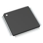 AD8114ASTZ
The activity of extra discounts on wholesale prices is in full swing…
Please fill in your contact information and we will send you the latest wholesale price list.





