 ChipApex | Global Electronic Components Supplier
SEARCH
Search Product
Search Post
— IC芯片 | 连接器 | 传感器 | 被动器件 —
Search productSearch post
— IC芯片 | 连接器 | 传感器 | 被动器件 —
Consult the customer manager about the wholesale price.
consultation hotline:86-132-6715-2157
email:[email protected]
Contact the product manager for consultation. One-stop consultation is available.
Do you want a lower wholesale price? Please send us your inquiry and we will reply immediately.
The AD9851BRS is a CMOS Direct Digital Synthesizer (DDS) featuring an 180 MHz clock rate and a selectable 6× reference clock multiplier. It integrates a high-performance 10-bit DAC and a high-speed comparator with hysteresis. The device accepts a 32-bit frequency tuning word, enabling precise frequency synthesis up to 72 MHz analog output or 200 MHz square wave output. Operating on a single supply from 2.7 V to 5.25 V, it supports simplified parallel or serial control interfaces. Key electrical specifications include a wideband SFDR of >43 dB at 70 MHz and residual phase noise of -132 dBc/Hz.
Verify the ordering suffix RS-28 corresponds to the Shrink Small Outline Package (SSOP) with 28 pins. Confirm the temperature range is industrial (-40°C to +85°C). Ensure the component matches the REV. D datasheet specifications for voltage levels and timing characteristics before integration into the design.
Select this model when an 180 MHz system clock is required for higher output frequency ranges compared to lower-speed DDS variants. The integrated 6× multiplier allows the use of lower-frequency reference clocks, simplifying board layout. Verify that the SSOP package option meets the thermal and physical constraints of the target application.
The AD9851 is part of Analog Devices' family of direct digital synthesizers, designed for applications requiring fast frequency switching and high spectral purity. It utilizes a proprietary angle rotation algorithm to convert phase accumulator data to DAC amplitude, minimizing ROM size while maintaining performance. This specific variant is optimized for industrial temperature ranges and standard surface-mount assembly.
The DS852 is documented as a potential replacement for the AD9851. Evaluate the DS852 based on its higher clock speed capabilities and power consumption differences. Ensure interface compatibility and verify that the substitute meets the specific jitter and SFDR requirements of the original design.
When enabled, the internal multiplier multiplies the external reference clock frequency by six to generate the system clock. For example, a 30 MHz input results in a 180 MHz system clock.
The comparator can toggle at frequencies up to 200 MHz when driven by a 1 V p-p input sine wave.
The full-scale output current is set by an external resistor connected to the RSET pin. The relationship is defined by IOUT = 39.93 / RSET.
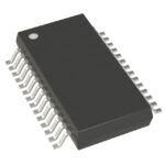 AD9851BRSZ
The activity of extra discounts on wholesale prices is in full swing…
Please fill in your contact information and we will send you the latest wholesale price list.





