 ChipApex | Global Electronic Components Supplier
SEARCH
Search Product
Search Post
— IC芯片 | 连接器 | 传感器 | 被动器件 —
Search productSearch post
— IC芯片 | 连接器 | 传感器 | 被动器件 —
Consult the customer manager about the wholesale price.
consultation hotline:86-132-6715-2157
email:[email protected]
Contact the product manager for consultation. One-stop consultation is available.
Do you want a lower wholesale price? Please send us your inquiry and we will reply immediately.
The Microchip Technology AR1020-I/SO is a resistive touch screen controller from the mTouch AR1000 Series, housed in a 20-SOIC package. It supports 4-wire, 5-wire, and 8-wire analog resistive sensors with a maximum 10-bit resolution. The device operates on a 2.5V to 5.0V supply and features I2C and SPI slave communication interfaces. Key specifications include a typical operating current of 3.0 mA (no touch) and 17 mA (touch), standby currents of 40 µA at 2.5V and 85 µA at 5V, and an industrial temperature range of -40°C to +85°C. It includes 128 bytes of user EEPROM for calibration storage.
Verify the specific interface configuration required for the design, as the AR1020 model supports both I2C and SPI slave modes. Confirm that the host system can accommodate the 50 µs delay requirement when clocking commands via I2C, as the AR1020 does not implement clock stretching during write conditions. Ensure the sensor tail connections match the selected wire type (4, 5, or 8-wire) and that unused sense pins are tied to VSS as specified in the hardware schematic.
Select the AR1020-I/SO for applications requiring support for multiple resistive sensor topologies within a single component. The SOIC-20 package is suitable for surface mount assembly. Consider the power requirements, noting that standby current varies significantly between 2.5V and 5V operation. Ensure the host microcontroller supports the necessary I2C or SPI protocols and can handle the open-drain interrupt signal on the SDO pin.
The AR1020-I/SO belongs to the Microchip mTouch AR1000 Series, which also includes variants like the AR1011 (UART) and AR1021 (I2C/SPI). The 'I' suffix indicates the industrial temperature range (-40°C to +85°C), while 'SO' denotes the 20-pin Small Outline Integrated Circuit package. This series is designed to offload processing overhead from the host by handling decoding and filtering internally.
Public confirmed substitute part numbers: AR1020T-I/SO (Tape & Reel version of the same package), AR1020-I/SS (Same function in SSOP package), AR1020T-I/SS (Tape & Reel SSOP version). Note that interface selection (I2C vs SPI) is determined by the M1 pin configuration for these variants.
The communication interface is selected via the M1 pin. Connecting M1 to VSS configures the device for I2C communications. For SPI mode, the M1 pin must be connected to VDD.
The WAKE pin serves three roles: wake-up from touch, touch detection, and measuring sensor capacitance. A 20 KΩ resistor is required between the WAKE pin and the X- pin for proper product operation.
No, the AR1020 does not implement clock stretching on write conditions. A 50 µs delay is needed before the Stop bit when clocking a command to the AR1020.
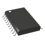 AR1020-I/SO
The activity of extra discounts on wholesale prices is in full swing…
Please fill in your contact information and we will send you the latest wholesale price list.






