 ChipApex | Global Electronic Components Supplier
SEARCH
Search Product
Search Post
— IC芯片 | 连接器 | 传感器 | 被动器件 —
Search productSearch post
— IC芯片 | 连接器 | 传感器 | 被动器件 —
Consult the customer manager about the wholesale price.
consultation hotline:86-132-6715-2157
email:[email protected]
Contact the product manager for consultation. One-stop consultation is available.
Do you want a lower wholesale price? Please send us your inquiry and we will reply immediately.
The Abracon ASSFLP-C04 is a programmable CMOS output clock oscillator designed for surface-mount applications. It operates within a frequency range of 8 MHz to 160 MHz and supports a supply voltage of 3.3V with standby functionality. The device utilizes a 4-SMD, no-lead ceramic package measuring 5.0 x 3.2 x 1.3 mm. Key electrical characteristics include a maximum rise time of 10 ns and a maximum fall time of 10 ns. It features tri-state capability and is compliant with RoHS standards, ensuring lead-free construction suitable for modern manufacturing processes.
Verify the specific frequency configuration and voltage requirements against the target design specifications before procurement. Confirm that the 3.3V supply rail aligns with the system power architecture. Ensure the 4-SMD footprint matches the PCB layout constraints. Check for RoHS compliance documentation if required by regulatory standards. Validate the tri-state logic levels with interfacing components.
Select this component when a programmable CMOS oscillator is required in a compact 5.0 x 3.2 mm package. Consider its spread spectrum capabilities for EMI reduction in sensitive digital circuits. Evaluate the 8 MHz to 160 MHz range against system clock needs. The 3.3V operation makes it suitable for standard logic families. Verify thermal performance within the -40°C to 85°C operating temperature range.
The ASSFLP series represents Abracon's line of programmable spread spectrum clock oscillators. These devices are engineered to minimize electromagnetic interference through frequency dithering. The C04 suffix denotes the specific package variant and operational parameters. This series targets portable electronics where size, power consumption, and signal integrity are critical design factors.
Cross-reference compatible models such as ASSVP1-R-C04 for similar form-factor requirements. Verify pin compatibility and electrical specifications before substitution. Ensure the replacement part supports the necessary frequency range and voltage levels. Confirm package dimensions match the existing PCB footprint.
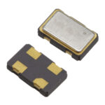 ASSFLP-C04
The activity of extra discounts on wholesale prices is in full swing…
Please fill in your contact information and we will send you the latest wholesale price list.




