 ChipApex | Global Electronic Components Supplier
SEARCH
Search Product
Search Post
— IC芯片 | 连接器 | 传感器 | 被动器件 —
Search productSearch post
— IC芯片 | 连接器 | 传感器 | 被动器件 —
Consult the customer manager about the wholesale price.
consultation hotline:86-132-6715-2157
email:[email protected]
Contact the product manager for consultation. One-stop consultation is available.
Do you want a lower wholesale price? Please send us your inquiry and we will reply immediately.
The AT42QT1040-MMHR is a digital burst mode charge-transfer capacitive sensor driver designed for touch-key applications. It supports up to four keys and provides four discrete open-drain outputs indicating individual key touch status. The device utilizes patented spread-spectrum charge-transfer technology in direct mode, enabling robust signal processing including self-calibration, auto drift compensation, and noise filtering. Operating within a supply voltage range of 1.8V to 5.5V, it features an operating temperature range from -40°C to +85°C. The component is housed in a 20-pin 3 x 3 mm VQFN package compliant with RoHS standards.
Verify the specific suffix 'MMHR' against official Microchip documentation to confirm tape-and-reel packaging details. Ensure the ordering information matches the required moisture sensitivity level and assembly trace codes. Cross-reference the manufacturer part number with current datasheet revisions to validate pinout compatibility and absolute maximum ratings before procurement.
Select this component for designs requiring up to four independent capacitive touch inputs with discrete logic outputs. Evaluate the electrode design and panel thickness to determine appropriate sample capacitor values, typically ranging from 2.2 nF to 22 nF. Consider the power consumption requirements relative to the chosen speed mode and AKS configuration when designing the power supply circuit.
The AT42QT1040 belongs to the QTouch family of capacitive sensor controllers developed by Atmel, now part of Microchip Technology. This series integrates advanced signal processing algorithms directly into the silicon, reducing the need for complex firmware development. The MMH suffix denotes the specific 20-pin VQFN package variant used for surface-mount assembly.
Consult official Microchip cross-reference lists for verified substitutes. Ensure any replacement maintains the same channel count, interface type, and package dimensions. Verify that alternative components support the required operating voltage and temperature ranges for the specific application environment.
AKS is enabled by connecting a 1 MΩ resistor between the SNSK0 pin and Vdd. Disabling AKS requires connecting the resistor to Vss.
Approximately 20 ms after power-up or reset, the OUT2 pin generates a low pulse lasting ~500 ns. System designers must account for this transient behavior.
The QT1040 uses asymmetric auto drift compensation. It adjusts the reference level faster for decreasing signals (~3 seconds) than for increasing signals (~1 second) to maintain sensitivity while avoiding false triggers.
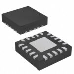 AT42QT1040-MMHR
The activity of extra discounts on wholesale prices is in full swing…
Please fill in your contact information and we will send you the latest wholesale price list.





