 ChipApex | Global Electronic Components Supplier
SEARCH
Search Product
Search Post
— IC芯片 | 连接器 | 传感器 | 被动器件 —
Search productSearch post
— IC芯片 | 连接器 | 传感器 | 被动器件 —
Consult the customer manager about the wholesale price.
consultation hotline:86-132-6715-2157
email:[email protected]
Contact the product manager for consultation. One-stop consultation is available.
Do you want a lower wholesale price? Please send us your inquiry and we will reply immediately.
The AWCDMC-2019V-7.5 is a two-line common mode choke manufactured by AW Coil, designed for through-hole mounting. It integrates both common-mode and differential-mode filtering capabilities within a single component. The device features an inductance of 7.5 mH measured at 10 kHz, with a leakage inductance of 280 µH. It supports a maximum current rating of 4.5 A and has a maximum DC resistance (DCR) of 100 mOhm. The AC voltage rating is specified at 250 V.
Verify the specific ordering suffix against official AW Coil documentation to confirm exact electrical tolerances and mechanical dimensions. Ensure the selected variant matches the required through-hole footprint and pin configuration for your design. Cross-reference the datasheet for thermal derating curves if operating near the 4.5 A maximum current limit. Confirm that the 250 V AC rating aligns with your system's peak voltage requirements.
Select this component when simultaneous common-mode and differential-mode attenuation is required without using separate filter stages. The 7.5 mH inductance value provides significant impedance at 10 kHz, suitable for lower-frequency noise suppression. Consider the 100 mOhm DCR limit for efficiency calculations in low-voltage, high-current applications. The integrated design reduces board space compared to discrete inductor arrangements.
This part belongs to the AWCDMC series from AW Coil, which specializes in integrated common-mode and differential-mode filters. The series offers various winding configurations and inductance values tailored for power-line applications. AW Coil designs these components to address complex electromagnetic interference challenges in modern electronic systems, providing precision-engineered magnetic solutions.
Direct substitutes must match the 7.5 mH inductance, 4.5 A current rating, and through-hole package type. Verify compatibility of the leakage inductance specification (280 µH) to ensure equivalent differential-mode performance. Check physical dimensions to confirm fit within the existing PCB layout constraints.
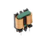 AWCDMC-2019V-7.5
The activity of extra discounts on wholesale prices is in full swing…
Please fill in your contact information and we will send you the latest wholesale price list.





