 ChipApex | Global Electronic Components Supplier
SEARCH
Search Product
Search Post
— IC芯片 | 连接器 | 传感器 | 被动器件 —
Search productSearch post
— IC芯片 | 连接器 | 传感器 | 被动器件 —
Consult the customer manager about the wholesale price.
consultation hotline:86-132-6715-2157
email:[email protected]
Contact the product manager for consultation. One-stop consultation is available.
Do you want a lower wholesale price? Please send us your inquiry and we will reply immediately.
The AZ23B27-G3-18 is a dual common anode silicon planar Zener diode array from the Vishay AZ23-G series, housed in a surface-mount SOT-23 package. It provides two independent Zener diodes sharing a common anode terminal. The nominal Zener voltage is 27 V with a tight tolerance of ±2%. Electrical characteristics are defined at a test current of 2 mA, featuring a maximum reverse leakage current of 50 nA and a dynamic resistance of 80 Ω. The device supports an operating temperature range from -55 °C to +150 °C and dissipates up to 300 mW on a standard FR-4 board.
Verify the complete ordering code matches the required specifications before procurement. Confirm that the suffix indicates the correct tape and reel quantity of 10,000 units per reel. Ensure compatibility with automated pick-and-place equipment utilizing 8 mm tape packaging. Cross-reference the manufacturer's latest datasheet revision to confirm current production status and any potential obsolescence notices.
Select this component when a dual Zener array with high precision is required in a compact footprint. The ±2% tolerance distinguishes it from the standard ±5% 'C' graded variants. Verify that the 2 mA test current aligns with the target circuit's biasing requirements. Consider the 80 Ω dynamic resistance for noise-sensitive designs and ensure the SOT-23 thermal dissipation limits are respected under maximum load conditions.
This part belongs to the AZ23-G series of small signal Zener diodes produced by Vishay General Semiconductor - Diodes Division. The series offers a wide range of Zener voltages from 2.2 V to 75 V in both ±5% and ±2% tolerances. The 'B' designation specifically denotes the tighter ±2% voltage tolerance grade compared to the standard 'C' grade devices within the same family.
AZ23B27-E3-18
The primary difference is the voltage tolerance. The AZ23B27-G3-18 has a ±2% tolerance, while the AZ23C27-G3-18 has a standard ±5% tolerance. Both share the same electrical parameters, package, and testing conditions.
In this dual common anode configuration, the anodes of both Zener diodes are connected internally to Pin 2 (the middle pin). This allows the cathodes (Pin 1 and Pin 3) to be used independently for clamping or regulation against a shared positive supply rail.
The maximum power dissipation is 300 mW when mounted on an FR-4 board with the recommended soldering footprint. The absolute maximum rating is 500 mW if the thermal resistance to lead is maintained at 250 K/W.
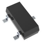 AZ23B27-G3-18
The activity of extra discounts on wholesale prices is in full swing…
Please fill in your contact information and we will send you the latest wholesale price list.




