 ChipApex | Global Electronic Components Supplier
SEARCH
Search Product
Search Post
— IC芯片 | 连接器 | 传感器 | 被动器件 —
Search productSearch post
— IC芯片 | 连接器 | 传感器 | 被动器件 —
Consult the customer manager about the wholesale price.
consultation hotline:86-132-6715-2157
email:[email protected]
Contact the product manager for consultation. One-stop consultation is available.
Do you want a lower wholesale price? Please send us your inquiry and we will reply immediately.
The AZ23B39-G3-08 is a dual common anode silicon planar Zener diode array from the Vishay AZ23-G series, housed in a SOT-23 surface-mount package. It features a nominal Zener voltage of 39 V with a tight ±2 % tolerance. The device operates at a test current of 0.5 mA and exhibits a maximum dynamic resistance of 87 Ω and a reverse leakage current of 50 μA at 29 V. Rated for power dissipation up to 500 mW on FR-4 boards, it supports an operating temperature range from -55 °C to +150 °C.
Verify the specific suffix '-G3-08' to confirm commercial grade status and standard reel quantity. Ensure compatibility with standard SOT-23 footprints during PCB layout. Confirm that the ±2 % tolerance meets the design requirements compared to the standard ±5 % variant.
Select this part when precise dual-channel voltage regulation is needed in a minimal footprint. The 39 V rating suits applications requiring higher threshold protection or reference levels. Consider the 0.5 mA test current for low-power designs rather than the 5 mA standard used for lower voltage variants.
This component belongs to the AZ23-G series of small signal Zener diodes manufactured by Vishay Semiconductors. The series covers a wide voltage range from 2.2 V to 75 V. The 'B' suffix indicates the tighter tolerance band, while the 'G3' denotes lead-free compliance and green material categorization.
AZ23C39-G3-08 offers identical electrical characteristics but with a wider ±5 % voltage tolerance. Other manufacturers may provide equivalent dual Zener arrays in SOT-23 packages, though pinout and exact impedance values should be verified against the datasheet.
The primary difference is the Zener voltage tolerance. AZ23B39 has a ±2 % tolerance, whereas AZ23C39 has a standard ±5 % tolerance. All other electrical parameters remain consistent.
Both internal Zener diodes share a single common anode terminal (Pin 3). This allows for independent cathode connections (Pins 1 and 2) to regulate two separate voltage rails or signals relative to the common ground/anode.
The maximum power dissipation is 500 mW when mounted on an FR-4 board with the recommended soldering footprint. The thermal resistance from junction to lead is specified at 250 K/W.
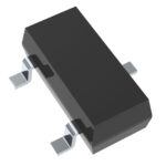 AZ23B39-G3-08
The activity of extra discounts on wholesale prices is in full swing…
Please fill in your contact information and we will send you the latest wholesale price list.




