 ChipApex | Global Electronic Components Supplier
SEARCH
Search Product
Search Post
— IC芯片 | 连接器 | 传感器 | 被动器件 —
Search productSearch post
— IC芯片 | 连接器 | 传感器 | 被动器件 —
Consult the customer manager about the wholesale price.
consultation hotline:86-132-6715-2157
email:[email protected]
Contact the product manager for consultation. One-stop consultation is available.
Do you want a lower wholesale price? Please send us your inquiry and we will reply immediately.
The AZ23C4V7-7-F is a dual surface mount Zener diode manufactured by Diodes Incorporated, housed in an SOT-23 package. It features a common anode configuration with two independent Zener elements. The nominal Zener voltage is 4.7 V, with a specified range of 4.4 V to 5.0 V at a test current (IZT) of 5.0 mA. Maximum power dissipation is rated at 300 mW, and the typical thermal resistance from junction to ambient air is 417 °C/W. The device operates within a temperature range of -65 °C to +150 °C. Electrical characteristics include a maximum Zener impedance (ZZT) of 78 Ω at IZT = 5.0 mA and a typical temperature coefficient of -0.015 %/°C.
Verify the complete part number includes the suffix '-7-F' for commercial grade availability in tape and reel packaging. Confirm that the specific application environment remains within the -65 °C to +150 °C operating temperature range. Ensure PCB pad layouts adhere to the manufacturer's recommended dimensions to maintain thermal performance and soldering integrity during assembly processes.
Select this component when a dual Zener solution with a common anode topology is required to minimize board space. The 4.7 V nominal voltage and 300 mW power rating suit low-current regulation tasks. Consider the negative temperature coefficient for thermal stability analysis. Verify that the 78 Ω maximum impedance meets the dynamic response requirements of the target circuit design.
This component belongs to the AZ23C series, which encompasses various Zener voltages ranging from 2.7 V to 51 V. All variants share the same SOT-23 footprint and 300 mW power dissipation capability. The series provides options for both common anode and common cathode configurations, allowing designers to choose based on polarity requirements while maintaining consistent mechanical and thermal characteristics across the product line.
Direct substitutes include other manufacturers' dual Zener arrays in SOT-23 packages with matching 4.7 V ratings and common anode configurations. Cross-referencing electrical parameters such as impedance and leakage current is essential. Ensure any replacement maintains compatibility with the existing PCB footprint and thermal management strategy.
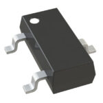 AZ23C4V7-7
The activity of extra discounts on wholesale prices is in full swing…
Please fill in your contact information and we will send you the latest wholesale price list.




