 ChipApex | Global Electronic Components Supplier
SEARCH
Search Product
Search Post
— IC芯片 | 连接器 | 传感器 | 被动器件 —
Search productSearch post
— IC芯片 | 连接器 | 传感器 | 被动器件 —
Consult the customer manager about the wholesale price.
consultation hotline:86-132-6715-2157
email:[email protected]
Contact the product manager for consultation. One-stop consultation is available.
Do you want a lower wholesale price? Please send us your inquiry and we will reply immediately.
The BA3835F-E2 is a silicon monolithic integrated circuit designed as a band-pass filter for spectrum analyzers in car audio systems. It supports five frequency bands: 105Hz, 340Hz, 1kHz, 3.4kHz, and 10.5kHz. The device operates on a 5V microcomputer power supply with a recommended voltage range of 4.5V to 6.5V. Key electrical parameters include a typical circuit current of 8.5mA, an input impedance of 100kΩ, and a common-mode rejection ratio of 50dB at 1kHz. The maximum output level is typically 4.8V, and the package type is SOP18.
Verify the exact ordering suffix against the manufacturer's official documentation to ensure compatibility with required packaging or temperature grades. Confirm that the component status aligns with long-term availability requirements for the intended production volume. Cross-reference pin assignments with the latest datasheet revision to prevent mounting errors during assembly.
Select this component when a dedicated five-band filter solution for 5V automotive audio systems is required. Ensure the application environment stays within the -25°C to +75°C operating temperature range. Verify that the load connected to the AOUT pin has sufficient input impedance to maintain the specified output levels without significant voltage drop.
The BA3835F-E2 belongs to ROHM's specialized analog IC lineup for consumer electronics, specifically targeting automotive audio enhancements. It integrates multiple band-pass filters into a single SOP18 package, reducing board space compared to discrete solutions. This integration supports compact designs in modern vehicle head units and dashboard displays.
No public confirmed substitute part numbers are available in the provided documentation. Any replacement must be evaluated based on identical pinout, voltage ratings, and frequency response characteristics. Consult ROHM sales representatives for potential obsolescence management or alternative recommendations.
The frequency characteristics are determined by the resistor connected between the RREF terminal and GND. For standard specifications, a 100kΩ resistor is used. Using a variable resistor allows for adjustment, though all bands will shift together.
The output offset voltage varies with the cycle time (Ts). If Ts is less than 50ms, the offset voltage increases due to transient characteristics of the peak hold circuit. A longer cycle time helps minimize this offset.
No, the device is not designed for radiation resistance or strong magnetic field environments. Operation in such conditions may cause malfunction, so adequate evaluation is necessary if such exposure is possible.
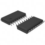 BA3835F-E2
The activity of extra discounts on wholesale prices is in full swing…
Please fill in your contact information and we will send you the latest wholesale price list.






