 ChipApex | Global Electronic Components Supplier
SEARCH
Search Product
Search Post
— IC芯片 | 连接器 | 传感器 | 被动器件 —
Search productSearch post
— IC芯片 | 连接器 | 传感器 | 被动器件 —
Consult the customer manager about the wholesale price.
consultation hotline:86-132-6715-2157
email:[email protected]
Contact the product manager for consultation. One-stop consultation is available.
Do you want a lower wholesale price? Please send us your inquiry and we will reply immediately.
The BA7657F-E2 is a triple-circuit video signal switcher designed for high-resolution display devices. It operates on a single 5 V power supply with a typical circuit current of 35 mA and a maximum rating of 8.0 V. The device features wide-range RGB signal switches with a cutoff frequency of 230 MHz, alongside dedicated switching circuits for HD and VD synchronization signals. A key functional block is the built-in separation (BUNRI) circuit that extracts synchronization signals superposed on the G signal. The component is housed in an SOP-24 package and supports an operating temperature range from -25°C to +75°C.
Verify the specific ordering suffix E2 to confirm the embossed tape and reel packaging format containing 2000 units per reel. Ensure compatibility with SOP-24 surface mount footprints during board layout. Confirm RoHS compliance status through official manufacturer documentation before finalizing procurement specifications.
Select this component when designing input blocks for advanced display devices requiring simplified RGB and synchronization signal routing. The integrated sync separation circuit reduces external component count compared to discrete solutions. Verify that the 230 MHz bandwidth meets the requirements for the target resolution and refresh rate applications.
The BA7657F belongs to ROHM's high-performance video signal switcher family, developed specifically for PC monitors and HDTVs. It shares architectural similarities with the BH7659FS but lacks the I2C bus switch and power-saving features found in the latter. This part focuses on analog RGB switching and digital sync handling within a single SOP-24 package.
Public confirmed substitute part numbers are not available in the provided documentation. Designers should consult ROHM directly for updated product availability or alternative recommendations if discontinuation occurs.
The block separates composite signals (Sync on Green) and outputs positive-electrode composite synchronization signals. If an HD signal is being input, a detector stops the separation circuit to prevent interference.
Insert an external resistance between 100 and 300 Ω near the output pins to suppress frequency peaks at high frequencies.
Applying a high-level voltage (≥1.8V) to the CTL pin selects Input 1, while applying a low-level voltage (≤1.2V) selects Input 2.
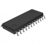 BA7657F-E2
The activity of extra discounts on wholesale prices is in full swing…
Please fill in your contact information and we will send you the latest wholesale price list.





