 ChipApex | Global Electronic Components Supplier
SEARCH
Search Product
Search Post
— IC芯片 | 连接器 | 传感器 | 被动器件 —
Search productSearch post
— IC芯片 | 连接器 | 传感器 | 被动器件 —
Consult the customer manager about the wholesale price.
consultation hotline:86-132-6715-2157
email:[email protected]
Contact the product manager for consultation. One-stop consultation is available.
Do you want a lower wholesale price? Please send us your inquiry and we will reply immediately.
The BD46402G-TR is a synchronous step-down DC/DC converter manufactured by Rohm Semiconductor. It integrates high-side and low-side N-channel MOSFETs to achieve efficient power conversion with an input voltage range of 2.7V to 5.5V. The device supports adjustable output voltages from 0.8V to 3.6V via an external resistor divider. It features a fixed switching frequency of 1.2MHz, enabling the use of small inductors and capacitors. The converter includes comprehensive protection mechanisms such as overcurrent protection, thermal shutdown, and soft-start functionality to ensure reliable operation under various load conditions.
Verify the specific suffix 'TR' indicates tape and reel packaging when ordering. Confirm the exact output voltage setting matches your design requirements using the external feedback resistors. Ensure the operating temperature range aligns with your application environment. Check the latest datasheet for any updates on recommended operating conditions and electrical characteristics before finalizing procurement.
Select this component when a compact solution with high efficiency is needed for low-voltage applications. The integrated MOSFETs reduce board space compared to discrete solutions. Consider the 1.2MHz frequency for balancing efficiency and component size. Verify that the input voltage source stays within the 2.7V to 5.5V range. Evaluate the thermal performance based on expected load currents and ambient temperatures.
This part belongs to Rohm's family of synchronous buck converters designed for portable electronics. It complements other models in the series offering different current capabilities or package options. The BD46402G-TR is optimized for applications where space constraints and power efficiency are critical priorities. It serves as a direct replacement for older asynchronous designs requiring similar voltage ranges.
Check for compatible pinouts and electrical specifications when substituting with other synchronous buck converters. Ensure the replacement part supports the required input voltage range and output current. Verify compatibility with existing PCB layout and passive component values. Consult manufacturer cross-reference lists for officially confirmed substitutes.
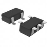 BD46402G-TR
The activity of extra discounts on wholesale prices is in full swing…
Please fill in your contact information and we will send you the latest wholesale price list.





