 ChipApex | Global Electronic Components Supplier
SEARCH
Search Product
Search Post
— IC芯片 | 连接器 | 传感器 | 被动器件 —
Search productSearch post
— IC芯片 | 连接器 | 传感器 | 被动器件 —
Consult the customer manager about the wholesale price.
consultation hotline:86-132-6715-2157
email:[email protected]
Contact the product manager for consultation. One-stop consultation is available.
Do you want a lower wholesale price? Please send us your inquiry and we will reply immediately.
The Texas Instruments BQ3285S-SB2TR is a CMOS real-time clock (RTC) module providing time-of-day, a 100-year calendar with automatic leap-year adjustment, and alarm features. It includes 114 bytes of general nonvolatile storage and three individually maskable interrupt sources. The device operates on a +5V supply (4.5V to 5.5V) with battery backup via the BC pin (2.5V to 4.0V). Key electrical parameters include a 160ns cycle time, less than 0.5μA load under battery operation, and support for both Intel and Motorola bus timing architectures.
Verify the specific suffix 'SB2TR' against current manufacturer documentation, as standard listings often indicate PLCC packages are discontinued. Confirm package type availability, as the datasheet specifies 24-pin DIP (P) or SOIC (S) options. Ensure the commercial temperature range (0°C to +70°C) meets system requirements. Check for end-of-life status or last-time-buy notices associated with older RTC families.
Select this component when a fully compatible drop-in replacement for legacy IBM AT architecture is required. Ensure the design accommodates the 24-pin package option (SOIC or DIP) and provides external connections for a 32.768kHz crystal and a 3V backup battery. Verify that the host processor can interface with the multiplexed address/data bus and supports the required Intel or Motorola timing signals.
The bq3285 is part of Texas Instruments' legacy real-time clock family designed for microprocessor peripherals. It serves as a direct functional equivalent to the National Semiconductor DP8573A and Dallas Semiconductor DS1285. The device integrates oscillator control, frequency division, and nonvolatile RAM management into a single CMOS chip, simplifying RTC implementation in personal computers and industrial controllers.
Functionally compatible substitutes include the DS1285 and MC146818A due to pin configuration matching. The bq3285E is an electrically similar variant within the same product line. Note that the 28-pin PLCC version is no longer available; verify if the SOIC or DIP package meets board layout constraints.
When VCC falls below the power-fail-detect voltage (VPFD, typically 4.17V), the device automatically write-protects the clock and storage registers. If VCC drops below the backup cell voltage (VBC, typically 3V), power switches to the BC pin to maintain data integrity and clock operation.
Only two external components are needed: a 32.768kHz quartz crystal (e.g., Daiwa DT-26) connected to X1-X2 pins, and a 3V backup battery connected to the BC pin.
Yes, the MOT pin selects the bus timing. Tying MOT to VCC enables Motorola timing, while tying it to VSS enables Intel timing. This setting should not be changed during system operation.
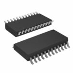 BQ3285S-SB2TR
The activity of extra discounts on wholesale prices is in full swing…
Please fill in your contact information and we will send you the latest wholesale price list.





