 ChipApex | Global Electronic Components Supplier
SEARCH
Search Product
Search Post
— IC芯片 | 连接器 | 传感器 | 被动器件 —
Search productSearch post
— IC芯片 | 连接器 | 传感器 | 被动器件 —
Consult the customer manager about the wholesale price.
consultation hotline:86-132-6715-2157
email:[email protected]
Contact the product manager for consultation. One-stop consultation is available.
Do you want a lower wholesale price? Please send us your inquiry and we will reply immediately.
The BU21010MUV-E2 is a capacitive sensor switch control IC manufactured by ROHM Semiconductor. It features an 8-channel serial interface and operates within a supply voltage range of 1.7 V to 3.3 V, with a typical operating voltage of 3.0 V. The device is housed in a VQFN-16 package (VQFN016V3030) and supports surface mount installation. It functions across a temperature range from -40°C to +85°C. The component utilizes a serial communication protocol for host interfacing and includes integrated power management capabilities.
Verify the current lifecycle status as the component is designated as obsolete or end-of-life. Confirm availability through authorized distributors, noting that stock may be limited or restricted. Ensure compliance with RoHS directives and check for any specific environmental documentation required for integration into final products.
Select this IC when designing systems requiring capacitive sensing with gesture support. Ensure the PCB layout accommodates separate analog and digital power domains. Verify that the overlay material thickness does not exceed recommended limits to maintain sensitivity. Consider the calibration requirements for paired sensor channels during the initial design phase.
This component belongs to the BU21010MUV series of capacitive sensor control ICs. It is designed to reduce host CPU load by integrating sensor data processing. The E2 suffix indicates packaging in embossed tape and reel format with a quantity of 3000 pieces per reel.
Publicly confirmed substitute part numbers are not available in the provided documentation. Due to the end-of-life status, alternative components must be evaluated based on channel count, interface compatibility, and package dimensions.
Only SIN0, SIN2, SIN4, and SIN6 have the gesture function capability; these cannot be changed to other sensor ports.
Odd ports do not perform direct calibration but use the results executed by their paired even-numbered ports (e.g., SIN1 uses SIN0's calibration result).
Power should be applied to DVDD first, then AVDD, or simultaneously. Applying AVDD before DVDD may prevent proper initialization.
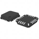 BU21010MUV-E2
The activity of extra discounts on wholesale prices is in full swing…
Please fill in your contact information and we will send you the latest wholesale price list.





