 ChipApex | Global Electronic Components Supplier
SEARCH
Search Product
Search Post
— IC芯片 | 连接器 | 传感器 | 被动器件 —
Search productSearch post
— IC芯片 | 连接器 | 传感器 | 被动器件 —
Consult the customer manager about the wholesale price.
consultation hotline:86-132-6715-2157
email:[email protected]
Contact the product manager for consultation. One-stop consultation is available.
Do you want a lower wholesale price? Please send us your inquiry and we will reply immediately.
The BU21029MUV-E2 is a 4-wire resistive touch screen controller IC from ROHM Semiconductor. It supports dual-touch detection and gesture recognition for standard 4-wire resistive screens. The device operates on a single power supply ranging from 1.65V to 3.60V. Key electrical specifications include a maximum standby current of 1.0 µA, typical sleep current of 100 µA, and typical operating current of 0.8 mA. It features a 12-bit coordinate resolution and communicates with the host processor via an I2C-like 2-wire serial interface. The component is housed in a VQFN020V4040 package measuring 4.00 mm x 4.00 mm x 1.00 mm.
Verify the specific ordering suffix E2 against the manufacturer's latest documentation to confirm compliance status and revision details. Confirm that the VQFN020V4040 package dimensions align with the target PCB footprint requirements. Ensure the host system voltage levels are compatible with the 1.65V to 3.60V operating range.
Select this component when dual-touch functionality is required for resistive displays. Ensure the host processor supports the I2C protocol for register access. Verify that the application environment stays within the -20°C to +85°C operating temperature range. Consider the low standby current if battery life is a critical design constraint.
The BU21029MUV belongs to the BU2102 series of resistive touch screen controllers designed by ROHM Semiconductor. This series focuses on generating data that enables dual touch detection, distinguishing it from standard single-point controllers. The E2 suffix typically denotes environmental compliance or specific manufacturing revisions within the product line.
Publicly confirmed substitute part numbers are not available in the provided source material. Designers should consult ROHM Semiconductor directly for obsolescence management or equivalent component recommendations.
The controller generates data based on prearranged touch screen parameters calibrated via registers 0x3 and 0x4. The host processor must execute calibration commands (CF=0101) to match the dual-touch circuit to the specific panel characteristics.
The INT pin provides an active-low interrupt signal to the host processor whenever a touch is detected. In automatic control mode, this signal is generated after the scan of the first touch is completed.
No. If the host processor will not actively control the reset function, the RSTB pin must be shorted to VDD to utilize the built-in power-on-reset circuit for initializing the registers upon power-up.
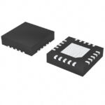 BU21029MUV-E2
The activity of extra discounts on wholesale prices is in full swing…
Please fill in your contact information and we will send you the latest wholesale price list.






