 ChipApex | Global Electronic Components Supplier
SEARCH
Search Product
Search Post
— IC芯片 | 连接器 | 传感器 | 被动器件 —
Search productSearch post
— IC芯片 | 连接器 | 传感器 | 被动器件 —
Consult the customer manager about the wholesale price.
consultation hotline:86-132-6715-2157
email:[email protected]
Contact the product manager for consultation. One-stop consultation is available.
Do you want a lower wholesale price? Please send us your inquiry and we will reply immediately.
The BU21051FS-E2 is a capacitive sensor control IC featuring two independent channels for switch applications. It integrates a 10-bit analog-to-digital converter, clock generation, and reset circuits within an SSOP-A16 package. The device operates on dual power supplies, AVDD and DVDD, both rated between 4.5V and 5.5V. Key electrical parameters include a typical standby current of 500µA, an internal CR oscillator frequency range of 0.9MHz to 2.5MHz, and a conversion time of 13µs at a 1MHz clock. The operating temperature range spans from -40°C to 85°C.
Verify the specific ordering suffix E2 corresponds to the embossed tape and reel packaging format containing 2500 pieces per reel. Confirm that the SSOP-A16 package dimensions and pinout match the design footprint requirements. Ensure compliance with RoHS directives as indicated in standard product documentation. Check for any recent revisions to the datasheet that may affect electrical characteristics or recommended operating conditions.
Select this component when designing systems requiring direct replacement of mechanical switches with capacitive sensors. The dual-channel architecture supports independent sensor inputs. Consider the available gain settings (x1 to x92) and filter options to balance detection sensitivity against reaction time. Verify that the system power supply can maintain the required 4.5V to 5.5V range for both analog and digital sections simultaneously.
This part belongs to ROHM's Capacitive Sensor Control IC Series, designed for general-use electronic equipment. It serves as a specialized interface solution for converting capacitance changes into digital switch signals. The series focuses on simplifying software control through integrated hardware features like automatic calibration and threshold comparison.
No public confirmed substitute part numbers are documented in the provided source material. Designers should consult ROHM sales representatives for alternative components if this specific package or feature set is unavailable.
When the SDN pin is set to 'L', the IC enters shutdown mode, halting all internal circuits. The device resumes operation when the SDN pin is set back to 'H'.
These pins allow users to set the voltage thresholds for detecting sensor ON and OFF states. Applying specific voltages, such as 1/2 VDD, enables precise calibration of the switch detection points.
Both AVDD and DVDD must be powered up either simultaneously or with DVDD first. The internal reset circuit monitors AVDD, so incorrect sequencing may cause initialization errors.
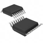 BU21051FS-E2
The activity of extra discounts on wholesale prices is in full swing…
Please fill in your contact information and we will send you the latest wholesale price list.





