 ChipApex | Global Electronic Components Supplier

SEARCH
Search Product
Search Post
— IC芯片 | 连接器 | 传感器 | 被动器件 —
Search productSearch post
— IC芯片 | 连接器 | 传感器 | 被动器件 —
Consult the customer manager about the wholesale price.
consultation hotline:86-132-6715-2157
email:[email protected]
Contact the product manager for consultation. One-stop consultation is available.
Do you want a lower wholesale price? Please send us your inquiry and we will reply immediately.
BY25D80ASTJG(R) is listed in the Memory IC range at ChipApex. The manufacturer field lists BYTe Semiconductor. Its product description is IC FLASH 8MBIT SPI/DUAL 8SOP. Review the specifications below when checking this part for your BOM.
The BY25D80AS is an 8M-bit SPI NOR Flash memory supporting Standard and Dual SPI interfaces. It operates on a single 2.7V to 3.6V supply. Key performance metrics include a Normal Read clock rate of 55MHz, Fast Read and Dual Read rates of 108MHz, and a maximum active current of 20mA. The device features a flexible architecture with 4KB sectors and 32/64KB blocks. Program/Erase speeds are characterized by a typical page program time of 0.7ms, sector erase of 100ms, block erase of 0.3s or 0.5s, and chip erase of 8s.
Verify the specific package variant (SOP8, TSSOP8, or USON8) required for your design, as the datasheet lists multiple options. Confirm the temperature grade (Commercial, Industrial -40 to +85°C, or Extended Industrial -40 to +105°C) matches your environmental specifications. Ensure the ordering suffix corresponds to the exact pin configuration and material compliance needed for your manufacturing process.
Select this component when an 8M-bit capacity is sufficient for application requirements. Choose based on the necessary interface speed; Dual SPI offers higher throughput than Standard SPI. Consider the operating temperature range required by your environment. Evaluate the package size constraints to determine between SOP8, TSSOP8, or USON8 form factors. Verify voltage compatibility with the 2.7V to 3.6V supply rail.
The BY25D80AS belongs to the BYTe Semiconductor SPI NOR Flash family. It shares architectural similarities with other devices in the series, such as the BY25Q16BSSIG and BY25D16ASSIG, which offer different densities like 16M-bit. These components generally utilize similar SPI command sets and protection features but differ in memory capacity and potentially supported package types.
Public confirmed substitute part numbers are not available in the provided documentation. Cross-referencing with other manufacturers requires independent verification of electrical characteristics and pinouts.
The device supports both hardware and software write protection. Hardware protection is activated by driving the /WP pin low, which locks the Status Register bits. Software protection allows selective locking of memory sectors or blocks via the BP2, BP1, and BP0 bits in the Status Register.
The Read Unique ID Number instruction accesses a factory-set, read-only 64-bit number unique to each device. This ID can be used by user software to prevent copying or cloning of the system.
A Power-On Reset (POR) circuit prevents inadvertent write operations. The device does not respond to instructions until VCC reaches the POR threshold voltage. After power-up, the device remains deselected until a falling edge is detected on the Chip Select (/CS) line.
Explore related parts through Memory, Integrated Circuits (ICs), all product categories, ChipApex homepage.
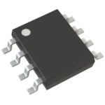 BY25D80ASTJG(R)

The activity of extra discounts on wholesale prices is in full swing…
Please fill in your contact information and we will send you the latest wholesale price list.





