 ChipApex | Global Electronic Components Supplier

SEARCH
Search Product
Search Post
— IC芯片 | 连接器 | 传感器 | 被动器件 —
Search productSearch post
— IC芯片 | 连接器 | 传感器 | 被动器件 —
Consult the customer manager about the wholesale price.
consultation hotline:86-132-6715-2157
email:[email protected]
Contact the product manager for consultation. One-stop consultation is available.
Do you want a lower wholesale price? Please send us your inquiry and we will reply immediately.
The CD74HC112M96 is a dual J-K negative-edge-triggered flip-flop from Texas Instruments, housed in a 16-pin SOIC package. It operates on a supply voltage range of 2 V to 6 V with a maximum clock frequency of 60 MHz. The device features asynchronous preset and clear inputs that override other logic states. Propagation delay is typically 30 ns at 6 V. It supports serial-to-parallel data transfer and includes set/reset functionality for reliable state control.
Verify the specific suffix 'M96' against the manufacturer's official datasheet to confirm packaging details and environmental compliance status. Ensure the selected variant matches the required pinout and thermal characteristics for your PCB layout. Cross-reference the ordering part number with the latest Texas Instruments product selection guide to avoid discrepancies in package dimensions or lead finish specifications.
Select this component when designing circuits requiring dual independent flip-flops with asynchronous control. The HC series offers standard CMOS compatibility and low power consumption suitable for battery-operated devices. Consider the 2 V to 6 V operating range for flexibility in system voltage architectures. Verify that the 16-pin SOIC package fits within the available board space and thermal constraints of the final assembly.
This device belongs to the Texas Instruments 74HC family of high-speed CMOS logic integrated circuits. The 74HC series is designed for general-purpose digital applications requiring fast switching speeds and low static power dissipation. The CD74HC112 specifically provides two J-K flip-flops in a single package, offering a compact solution for sequential logic design compared to discrete components.
Low-level signals on the preset (/PRE) or clear (/CLR) inputs immediately set or reset the output, overriding the J, K, and clock inputs regardless of their current states.
The flip-flops are triggered on the negative-going edge (falling edge) of the clock pulse, transferring data from the J and K inputs to the outputs.
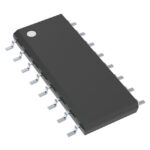 CD74HC112M96

The activity of extra discounts on wholesale prices is in full swing…
Please fill in your contact information and we will send you the latest wholesale price list.





