 ChipApex | Global Electronic Components Supplier
SEARCH
Search Product
Search Post
— IC芯片 | 连接器 | 传感器 | 被动器件 —
Search productSearch post
— IC芯片 | 连接器 | 传感器 | 被动器件 —
Consult the customer manager about the wholesale price.
consultation hotline:86-132-6715-2157
email:[email protected]
Contact the product manager for consultation. One-stop consultation is available.
Do you want a lower wholesale price? Please send us your inquiry and we will reply immediately.
The DDA114EH-7 is a dual pre-biased PNP small signal surface mount transistor manufactured by Diodes Incorporated. It utilizes epitaxial planar die construction and is housed in an SOT563 case. The device features built-in biasing resistors with nominal values of R1 = 10 kΩ and R2 = 22 kΩ. Key electrical parameters include a collector-emitter breakdown voltage (BVCEO) of -50 V, a maximum output current (IC) of -100 mA, and a power dissipation (PD) of 150 mW at +25°C. The DC current transfer ratio (hFE) ranges from 100 to 600 at IC = -1mA and VCE = -5V. The gain-bandwidth product (fT) is typically 250 MHz. Operating and storage temperatures range from -55°C to +150°C.
Verify the specific ordering suffix '-7' corresponds to the standard reel packaging containing 3,000 units per 7-inch reel. Confirm that the component marking code 'P13' matches the required identification for production integration. Ensure compliance with moisture sensitivity level 1 requirements during handling and soldering processes according to J-STD-020 standards.
Select this component when a dual PNP pre-biased transistor with a 10kΩ base resistor is required. Verify that the -50V collector-emitter breakdown voltage meets the circuit's supply voltage constraints. Consider the 150mW power dissipation limit and thermal resistance of 833°C/W for adequate heat management in the intended application environment.
This part belongs to the DDAxxxxH series of PNP pre-biased dual transistors from Diodes Incorporated. It is electrically complementary to the NPN DDC114EH-7 variant within the same family. The H-series designation indicates specific resistor ratios and performance characteristics tailored for general-purpose switching and amplification tasks in compact surface-mount designs.
Direct functional substitutes within the same manufacturer line include DDA114TH-7, which shares the SOT563 package but differs in internal resistor values (R1=10kΩ, R2=47kΩ). Designers must verify that alternative resistor ratios do not alter the input drive requirements or switching thresholds of the existing circuit design.
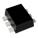 DDA114EH-7
The activity of extra discounts on wholesale prices is in full swing…
Please fill in your contact information and we will send you the latest wholesale price list.




