 ChipApex | Global Electronic Components Supplier

SEARCH
Search Product
Search Post
— IC芯片 | 连接器 | 传感器 | 被动器件 —
Search productSearch post
— IC芯片 | 连接器 | 传感器 | 被动器件 —
Consult the customer manager about the wholesale price.
consultation hotline:86-132-6715-2157
email:[email protected]
Contact the product manager for consultation. One-stop consultation is available.
Do you want a lower wholesale price? Please send us your inquiry and we will reply immediately.
DG2618DN-T1-E4 is listed in the Analog Switches, Multiplexers, Demultiplexers range at ChipApex. The manufacturer field lists Vishay Siliconix. Its product description is IC SWITCH SPDT X 2 7OHM 10DFN. Review the specifications below when checking this part for your BOM.
The DG2618DN-T1-E4 is a low voltage, dual SPDT analog switch manufactured by Vishay Siliconix. It features an integrated charge pump circuit that enables operation with a supply voltage range of 1.5 V to 3.6 V while maintaining low on-resistance. The device provides two independent channels in a DFN-10 package. Key electrical parameters include a maximum turn-on time of 76 ns and a maximum turn-off time of 41 ns at full temperature range. On-resistance reaches up to 8.0 Ω under worst-case conditions. Power supply current is limited to 300 µA maximum.
Verify the specific ordering suffix against the manufacturer's official documentation to confirm compliance with lead-free termination requirements and RoHS standards. Ensure the component matches the specified DFN-10 package dimensions and thermal characteristics required for the target application design.
Select this component when designing portable or battery-powered circuits requiring low voltage analog signal routing. The built-in charge pump allows for reduced power consumption compared to standard switches. Verify that the system logic levels align with the specified input high and low voltage thresholds for reliable switching performance.
This part belongs to the DG2616/DG2617/DG2618 family of low voltage analog switches. All variants share identical physical packages and core switching capabilities, differing primarily in their internal logic configurations and shutdown pin functionalities as defined in the official datasheet.
DG2616DN-T1-E4
Signals on the IN, COM, NC, or NO pins that exceed V+ are clamped by internal diodes. Designers must limit the forward diode current to the maximum current ratings specified in the absolute maximum ratings table.
Break-before-make timing is guaranteed for the DG2618. This ensures that one channel turns off before the other turns on, preventing momentary short circuits between outputs.
Yes, the device offers high bandwidth characteristics. At 1 MHz, off-isolation is typically -77 dB and crosstalk is -80 dB, making it suitable for audio and video signal routing applications.
Explore related parts through Interface, Integrated Circuits (ICs), all product categories, ChipApex homepage.
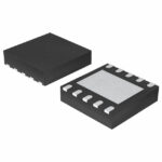 DG2618DN-T1-E4

The activity of extra discounts on wholesale prices is in full swing…
Please fill in your contact information and we will send you the latest wholesale price list.





