 ChipApex | Global Electronic Components Supplier
SEARCH
Search Product
Search Post
— IC芯片 | 连接器 | 传感器 | 被动器件 —
Search productSearch post
— IC芯片 | 连接器 | 传感器 | 被动器件 —
Consult the customer manager about the wholesale price.
consultation hotline:86-132-6715-2157
email:[email protected]
Contact the product manager for consultation. One-stop consultation is available.
Do you want a lower wholesale price? Please send us your inquiry and we will reply immediately.
The DS1075M-80 is a fixed-frequency oscillator and divider from the DS1075 series, manufactured by Analog Devices (Maxim Integrated). It operates on a single 5V supply and generates clock signals in the range of approximately 30 KHz to 100 MHz. The device features dual outputs: OUT0 serves as a reference output, while IN/OUT provides the primary clock signal. Key electrical specifications include an initial frequency tolerance of ±0.5%, combined frequency variation over temperature and voltage of ±1%, and a typical supply current of 50 mA at VCC = 5V. The unit is housed in an 8-pin DIP package.
Verify the specific suffix 'M' corresponds to the 300-mil DIP package when sourcing replacements. Confirm that the '-80' designation matches the required 80.000 MHz maximum operating frequency. Check manufacturer documentation for end-of-life status, as this component may be discontinued. Ensure programming hardware compatibility with the 1-Wire protocol if field reprogramming is necessary.
Select the DS1075M-80 when a fixed 80 MHz clock source is needed with high initial accuracy. Consider the DIP package only if through-hole mounting is mandatory. Evaluate the need for synchronous output enable versus simple power-down control based on system timing requirements. Verify that the load capacitance requirements (typically 15 pF) align with the connected circuitry to maintain specified jitter and duty cycle performance.
The DS1075M-80 belongs to the DS1075 EconOscillator family, which includes variants like the DS1075-100 (100 MHz), DS1075-66 (66.667 MHz), and DS1075-60 (60 MHz). The 'M' suffix specifically denotes the 300-mil DIP package option, distinct from the SOIC package variant. This family allows for flexible frequency configuration through internal registers rather than external resonators.
Direct functional substitutes within the same family include DS1075-100, DS1075-66, and DS1075-60, provided the frequency difference is acceptable. For package-specific replacement, ensure the alternative part supports the 8-pin DIP form factor. Cross-reference with newer Maxim Integrated clock generator families if the DS1075 is no longer available, verifying pinout and register compatibility.
Programming mode is initiated by powering up the device with a pull-up resistor (approximately 5 kΩ) connected between the IN/OUT pin and the VCC supply pin. This pulls the pin above VIH during power-up, triggering the internal programming sequence.
OUT0 provides a buffered output of the master reference clock (internal or external/crystal). It is unaffected by the Output Enable (OE) pin but is disabled during the power-down sequence. It can be permanently disabled by setting the EN0 bit to 1 to reduce power consumption.
The OE pin provides synchronous output gating. When OE is high, the oscillator runs freely. When OE goes low, the output is held low until the next high-to-low transition of the output signal, preventing pulse truncation. During this time, internal counters reset to maintain phase relationship upon re-enablement.

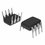 DS1075M-80
The activity of extra discounts on wholesale prices is in full swing…
Please fill in your contact information and we will send you the latest wholesale price list.



