 ChipApex | Global Electronic Components Supplier
SEARCH
Search Product
Search Post
— IC芯片 | 连接器 | 传感器 | 被动器件 —
Search productSearch post
— IC芯片 | 连接器 | 传感器 | 被动器件 —
Consult the customer manager about the wholesale price.
consultation hotline:86-132-6715-2157
email:[email protected]
Contact the product manager for consultation. One-stop consultation is available.
Do you want a lower wholesale price? Please send us your inquiry and we will reply immediately.
The DS1081LE+ is a spread-spectrum clock modulator IC designed to reduce electromagnetic interference (EMI) in digital electronic equipment. It accepts an input clock signal between 20MHz and 134MHz and generates a center-dithered output using an integrated phase-locked loop (PLL). The device operates on a single 3V to 3.6V supply, consumes approximately 15mA at maximum frequency, and features low cycle-to-cycle jitter of 75ps. It is housed in an 8-pin TSSOP package and supports an extended temperature range from -40°C to +125°C.
Verify the component grade matches the required operating temperature range (-40°C to +125°C) for automotive or industrial applications. Confirm that the 8-TSSOP footprint aligns with the PCB land pattern specifications provided in the datasheet. Ensure decoupling capacitors are placed close to the VCC and GND pins to maintain signal integrity.
Select the DS1081LE+ when system design requires active EMI suppression through clock dithering without altering rise/fall times. Choose this part if the application demands a single 3.3V supply and pin-compatible replacement for specific legacy devices. Verify that the input clock frequency falls within the 20MHz to 134MHz operational window.
The DS1081LE+ belongs to the DS1081L series of spread-spectrum clock modulators manufactured by Analog Devices Inc./Maxim Integrated. The 'E' suffix indicates the extended industrial temperature rating (-40°C to +125°C), while the '+' denotes lead-free and RoHS-compliant packaging. This component is distinct from standard clock generators as it actively modulates frequency to spread spectral energy.
The datasheet notes pin compatibility with the Alliance/PulseCore Semiconductor P2040 series devices. Verify electrical parameters such as supply voltage and output drive strength against these alternatives before substitution.
The dither magnitude is configured using the SMSEL1 and SMSEL2 input pins. Logic levels determine the selection: 0/0 for ±2.0%, 0/1 for ±1.5%, 1/0 for ±1.0%, and 1/1 for ±0.5%.
The SSEN pin controls the spread-spectrum enable state. Pulling it high disables modulation but keeps the PLL active; leaving it open three-states the output. On power-up, the output remains three-stated until the PLL stabilizes.
The dither rate is set by the CRSEL pin and depends on the input clock frequency (fIN). For 66-134MHz, the rate is fIN/2048; for 33-80MHz, it is fIN/1024; and for 20-38MHz, it is fIN/512.
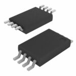 DS1081LE+
The activity of extra discounts on wholesale prices is in full swing…
Please fill in your contact information and we will send you the latest wholesale price list.





