 ChipApex | Global Electronic Components Supplier

SEARCH
Search Product
Search Post
— IC芯片 | 连接器 | 传感器 | 被动器件 —
Search productSearch post
— IC芯片 | 连接器 | 传感器 | 被动器件 —
Consult the customer manager about the wholesale price.
consultation hotline:86-132-6715-2157
email:[email protected]
Contact the product manager for consultation. One-stop consultation is available.
Do you want a lower wholesale price? Please send us your inquiry and we will reply immediately.
DS1124U-25+ is listed in the Delay Lines IC range at ChipApex. The manufacturer field lists Analog Devices Inc./Maxim Integrated. Its product description is IC DEL LN 256TAP 83.75NS 10UMAX. Review the specifications below when checking this part for your BOM.
The DS1124U-25+ is an 8-bit programmable timing element housed in a 10-pin µSOP package. It provides 256 delay intervals with a nominal step size of 0.25ns, achieving total delays from 20ns to 84ns. The device operates on a single 5.0V supply (4.75V to 5.25V) and features a 3-wire serial interface for programming. Key electrical parameters include a maximum serial clock frequency of 10MHz, active current up to 30mA, and output drive capabilities of -1mA high-level and 8mA low-level. It supports input frequencies up to 10MHz with minimum pulse widths of 40ns.
Verify the specific suffix designation when ordering. The absence of a trailing character indicates cut tape packaging, while the 'T' suffix denotes tape and reel configuration. Confirm that the component meets lead-free and RoHS compliance standards required by the target assembly process. Ensure the operating temperature range aligns with the system environment specifications.
Select this component when precise sub-nanosecond delay adjustments are necessary within a 5V logic environment. The 3-wire interface minimizes microcontroller pin usage compared to parallel alternatives. Consider the integral nonlinearity specifications if strict linearity across all 256 steps is critical for the application timing requirements.
This part belongs to the DS1124 series of programmable delay lines manufactured by Analog Devices / Maxim Integrated. It serves as a functional alternative to the DS1021-25 model. The device integrates an 8-bit latch and shift register architecture to manage the delay settings efficiently without requiring external memory components.
The DS1021-25 is documented as a similar functional device. Verify pin compatibility and electrical characteristics before substitution. No other direct substitute part numbers are confirmed in the provided documentation.
The Q pin outputs the current register value during serial clocking. To prevent destructive reads, the data from Q must be written back to the D input using a feedback resistor or separate I/O pins.
A settling time (tEDV) of 50µs is required after pulling the Enable (E) pin low before the signal delay meets its specified accuracy.
Yes, multiple devices can be cascaded on the same 3-wire bus. Software must shift bits for all connected devices during each read or write cycle to maintain correct settings.
Explore related parts through Clock/Timing, Integrated Circuits (ICs), all product categories, ChipApex homepage.
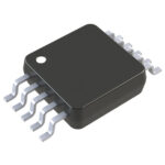 DS1124U-25+

The activity of extra discounts on wholesale prices is in full swing…
Please fill in your contact information and we will send you the latest wholesale price list.






