 ChipApex | Global Electronic Components Supplier
SEARCH
Search Product
Search Post
— IC芯片 | 连接器 | 传感器 | 被动器件 —
Search productSearch post
— IC芯片 | 连接器 | 传感器 | 被动器件 —
Consult the customer manager about the wholesale price.
consultation hotline:86-132-6715-2157
email:[email protected]
Contact the product manager for consultation. One-stop consultation is available.
Do you want a lower wholesale price? Please send us your inquiry and we will reply immediately.
The DZ23C10-HE3_A-08 is a silicon planar Zener diode from the Vishay DZ23 series, housed in an SOT-23 surface-mount package. It features a nominal Zener voltage of 10 V with a ±5 % tolerance and operates at a test current of 5 mA. The device has a maximum reverse leakage current of 0.1 µA at 7.5 V and a dynamic resistance of 15 Ω at 5 mA. It is qualified to AEC-Q101 standards for automotive applications, supports a junction temperature up to 150 °C, and provides ESD protection exceeding 8 kV via the human body model.
Verify that the ordering suffix matches HE3_A-08 to confirm AEC-Q101 qualification. Ensure the component is sourced from authorized distributors to guarantee authenticity. Cross-reference the datasheet revision against the manufacturing date code to validate compliance with the latest electrical specifications and RoHS standards before finalizing procurement orders.
Select this component when a 10 V reference with ±5 % tolerance is required in an SOT-23 footprint. Confirm that the operating environment does not exceed the 150 °C junction temperature limit. Verify that the 5 mA test current aligns with the target circuit design. Consider the 15 Ω dynamic resistance for precision requirements in low-current applications.
This part belongs to the DZ23 series of small-signal Zener diodes manufactured by Vishay Semiconductors. The series covers a wide voltage range from 2.2 V to 75 V. The HE3_A suffix specifically denotes the AEC-Q101 qualified variant, distinguishing it from the commercial grade E3 versions within the same physical package and electrical family.
Direct replacements must match the 10 V nominal voltage, SOT-23 package, and AEC-Q101 qualification. Verify that alternative manufacturers provide equivalent dynamic resistance and leakage current specifications to ensure circuit compatibility without redesigning the bias network.
The DZ23C10-HE3_A-08 has a standard Zener voltage tolerance of ±5 %, resulting in a specified range of 9.50 V to 10.50 V.
The component meets AEC-Q101 ESD capability standards, offering protection greater than 8 kV according to the human body model and greater than 800 V according to the machine model.
When mounted on an FR-4 board with the recommended soldering footprint, the maximum power dissipation is limited to 300 mW.
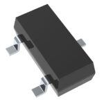 DZ23C10-HE3_A-08
The activity of extra discounts on wholesale prices is in full swing…
Please fill in your contact information and we will send you the latest wholesale price list.




