 ChipApex | Global Electronic Components Supplier

SEARCH
Search Product
Search Post
— IC芯片 | 连接器 | 传感器 | 被动器件 —
Search productSearch post
— IC芯片 | 连接器 | 传感器 | 被动器件 —
Consult the customer manager about the wholesale price.
consultation hotline:86-132-6715-2157
email:[email protected]
Contact the product manager for consultation. One-stop consultation is available.
Do you want a lower wholesale price? Please send us your inquiry and we will reply immediately.
The EQY-1-63+ is a fixed slope gain equalizer MMIC from Mini-Circuits, designed for RF applications spanning DC to 6000 MHz. It provides a nominal 1.2 dB die-fixed negative gain slope to compensate for frequency-dependent losses in transmission lines and passive components. The device operates on a single positive supply voltage and features an internal bias network for simplified integration. Packaged in an 8-TFDFN exposed pad surface-mount package, it ensures reliable performance across industrial temperature ranges.
Verify the complete part number including the '+' suffix to ensure RoHS compliance. Confirm the specific package variant matches the design footprint. Check the latest datasheet for updated electrical specifications and thermal recommendations. Ensure the supplier provides original manufacturer documentation. Validate compatibility with system impedance requirements before procurement.
Select this component when a fixed negative slope compensation is required within the DC to 6 GHz range. Consider the 1.2 dB slope magnitude relative to the target loss profile of the transmission medium. Evaluate the power consumption and supply voltage constraints against system capabilities. Assess the thermal dissipation requirements given the small form factor package. Compare alternative slope values if the specific attenuation characteristic does not match the application needs.
This component belongs to the EQY series of gain equalizers from Mini-Circuits. These devices are monolithic microwave integrated circuits (MMICs) designed for flatness correction in RF systems. The series offers various slope options to address different loss characteristics in interconnects. They are commonly used in communication infrastructure and test equipment to maintain signal integrity across wide bandwidths.
Direct substitutes include other Mini-Circuits EQY models with similar slope characteristics, such as EQY-1-45+ or EQY-1-90+. Verify that any replacement maintains the same 50-ohm impedance and operating frequency range. Ensure the pinout and package dimensions are compatible with the existing PCB layout. Cross-reference datasheets for matching S-parameter performance.
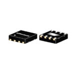 EQY-1-63+

The activity of extra discounts on wholesale prices is in full swing…
Please fill in your contact information and we will send you the latest wholesale price list.





