 ChipApex | Global Electronic Components Supplier

SEARCH
Search Product
Search Post
— IC芯片 | 连接器 | 传感器 | 被动器件 —
Search productSearch post
— IC芯片 | 连接器 | 传感器 | 被动器件 —
Consult the customer manager about the wholesale price.
consultation hotline:86-132-6715-2157
email:[email protected]
Contact the product manager for consultation. One-stop consultation is available.
Do you want a lower wholesale price? Please send us your inquiry and we will reply immediately.
The Taiwan Semiconductor GBL005 is a single-phase bridge rectifier within the GBL series, rated for a maximum average forward current of 4 A and a repetitive peak reverse voltage of 50 V. It utilizes glass passivated chip junctions to achieve low leakage currents, typically less than 0.1 μA at room temperature. The device operates with a junction temperature range from -55 °C to +150 °C and withstands surge peak forward currents up to 150 A. Electrical characteristics include a maximum forward voltage of 1.1 V at 4 A and a typical junction-to-ambient thermal resistance of 32 °C/W.
Verify the specific ordering code suffix when purchasing. The standard package designation is GBLx, while the 'H' suffix indicates AEC-Q101 automotive qualification. Confirm that the component matches the required voltage rating and packaging format before integration into production systems.
Select the GBL005 specifically for circuits requiring a 50 V reverse voltage rating. Higher voltage variants in the series, such as GBL01 or GBL02, offer increased blocking capabilities but may not be necessary for lower voltage designs. Ensure the thermal management design accounts for the specified junction-to-ambient resistance under expected load conditions.
This component belongs to the GBL series of standard bridge rectifiers manufactured by Taiwan Semiconductor. The series covers a wide voltage range from 50 V to 1000 V, sharing common mechanical dimensions and features like the GBL case style. The GBL005 represents the lowest voltage option in this specific lineup.
Direct substitutes must match the 4 A current rating, 50 V reverse voltage, and GBL package footprint. Verify that alternative components meet the same thermal and electrical specifications for seamless replacement.
Standard versions are not explicitly listed as automotive qualified. Only the variant with the 'H' suffix (GBL005H) is designated as AEC-Q101 qualified.
The device can withstand a surge peak forward current of 150 A for an 8.3 ms single half sine-wave superimposed on the rated load.
Polarity is marked directly on the body of the component, following the standard marking diagram provided in the datasheet.
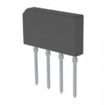 GBL005

The activity of extra discounts on wholesale prices is in full swing…
Please fill in your contact information and we will send you the latest wholesale price list.




