 ChipApex | Global Electronic Components Supplier

SEARCH
Search Product
Search Post
— IC芯片 | 连接器 | 传感器 | 被动器件 —
Search productSearch post
— IC芯片 | 连接器 | 传感器 | 被动器件 —
Consult the customer manager about the wholesale price.
consultation hotline:86-132-6715-2157
email:[email protected]
Contact the product manager for consultation. One-stop consultation is available.
Do you want a lower wholesale price? Please send us your inquiry and we will reply immediately.
The GBLA06-E3/51 is a glass passivated single-phase bridge rectifier manufactured by Vishay General Semiconductor - Diodes Division. It features an in-line circuit configuration within the GBL package. The device supports a maximum repetitive peak reverse voltage of 600 V and a maximum average forward rectified output current of 4.0 A at a case temperature of 50 °C, or 3.0 A at an ambient temperature of 40 °C. It exhibits a typical instantaneous forward voltage drop of 1.0 V at 4.0 A and a maximum DC reverse current of 5 μA at rated blocking voltage. The unit withstands a peak forward surge current of 120 A and operates within a junction and storage temperature range of -55 to +150 °C.
Verify component authenticity through authorized distributors or direct manufacturer channels. Confirm compliance with RoHS directives and check for specific packaging requirements such as anti-static PVC trays. Validate that the ordering suffix matches the required delivery mode and base quantity specifications before finalizing procurement orders.
Select this component based on the 600 V reverse voltage rating and 4.0 A continuous current capacity. Ensure thermal management aligns with the specified derating curves for both heat-sink mounting and PCB configurations. Verify that the operating environment remains within the -55 to +150 °C junction temperature limits for reliable performance.
This part belongs to the GBLAxx series of glass passivated single-phase bridge rectifiers. The series includes variants with different voltage ratings ranging from 50 V to 1000 V, all sharing the same GBL package outline and general electrical characteristics. The E3 suffix indicates RoHS compliance and halogen-free status.
The official alternative device listed in the datasheet is the GBL06E series. Designers should verify pinout compatibility and ensure the replacement meets the original 600 V and 4.0 A specifications.
The maximum repetitive peak reverse voltage (VRRM) is 600 V.
The current is rated at 4.0 A at a case temperature of 50 °C, but derates to 3.0 A at an ambient temperature of 40 °C when mounted on a PCB.
The typical thermal resistance (RθJA) is 47 °C/W when mounted on a PCB with 0.375-inch lead length and 0.5 x 0.5 inch copper pads.
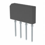 GBLA06-E3/51

The activity of extra discounts on wholesale prices is in full swing…
Please fill in your contact information and we will send you the latest wholesale price list.





