ChipApex | Global Electronic Components Supplier

SEARCH
Search Product
Search Post
— IC芯片 | 连接器 | 传感器 | 被动器件 —
Search productSearch post
— IC芯片 | 连接器 | 传感器 | 被动器件 —
Consult the customer manager about the wholesale price.
consultation hotline:86-132-6715-2157
email:[email protected]
Contact the product manager for consultation. One-stop consultation is available.
Do you want a lower wholesale price? Please send us your inquiry and we will reply immediately.
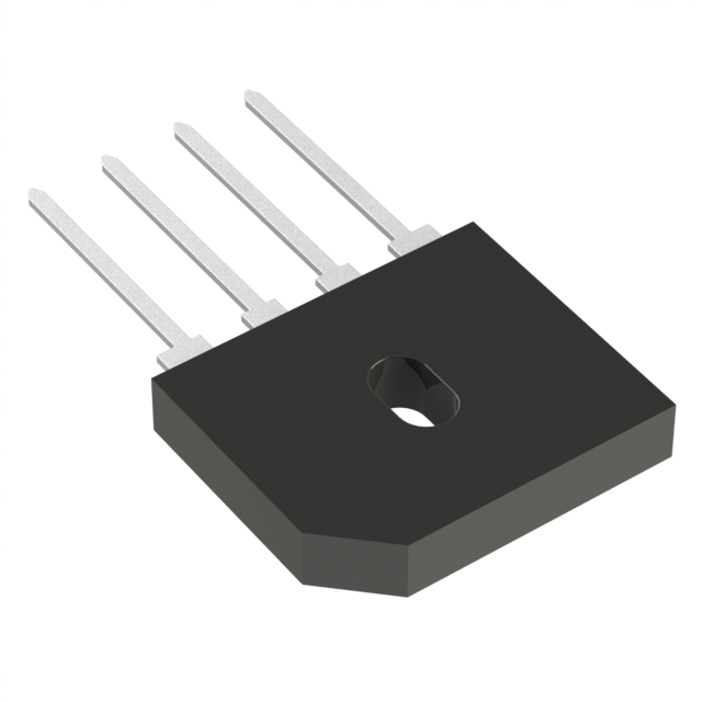
The GBU10K-LV is a low forward voltage single-phase diode bridge rectifier manufactured by Diotec Semiconductor. It features an average forward current (IFAV) of 10 A and a repetitive peak reverse voltage (VRRM) of 1000 V. The typical forward voltage drop (VF) is 0.87 V at 25°C with a 10 A load. Peak forward surge currents are rated at 200 A for 50 Hz and 220 A for 60 Hz half-sine waves. The device operates within a junction and storage temperature range of -50°C to +150°C, with thermal resistances of 2.7 K/W (junction-to-case) and 18 K/W (junction-to-ambient).
Verify the specific ordering suffix against official Diotec documentation to confirm package type and compliance status. Ensure that the selected component meets the required electrical ratings for the target application environment. Cross-reference datasheet parameters with actual circuit requirements before finalizing procurement decisions.
Select this component when a standard bridge rectifier requires reduced conduction losses. The low VF characteristic makes it suitable for applications where thermal management is critical. Verify that the 1000 V reverse voltage rating exceeds the maximum expected line voltage peaks in the system design.
This part belongs to the GBU series of single-phase bridge rectifiers from Diotec Semiconductor. The GBU series utilizes a molded plastic case designed for through-hole mounting on printed circuit boards. The 'LV' designation specifically indicates a low forward voltage variant optimized for improved energy efficiency compared to standard versions.
Check for direct replacements within the GBU series offering similar current and voltage ratings. Verify pinout compatibility and physical dimensions if substituting with components from other manufacturers. Ensure thermal resistance characteristics match the existing heat dissipation design.
The typical forward voltage drop is 0.87 V at a junction temperature of 25°C and a forward current of 10 A.
The peak forward surge current is rated at 200 A for a 50 Hz half-sine wave and 220 A for a 60 Hz half-sine wave.
The protective resistance Rt is calculated as VRRM divided by IFSM to ensure the surge current limit is not exceeded during capacitor charging.
 GBU10K-LV

The activity of extra discounts on wholesale prices is in full swing…
Please fill in your contact information and we will send you the latest wholesale price list.