 ChipApex | Global Electronic Components Supplier
SEARCH
Search Product
Search Post
— IC芯片 | 连接器 | 传感器 | 被动器件 —
Search productSearch post
— IC芯片 | 连接器 | 传感器 | 被动器件 —
Consult the customer manager about the wholesale price.
consultation hotline:86-132-6715-2157
email:[email protected]
Contact the product manager for consultation. One-stop consultation is available.
Do you want a lower wholesale price? Please send us your inquiry and we will reply immediately.
The HMC892LP5ETR is a monolithic microwave integrated circuit (MMIC) bandpass filter featuring user-selectable passband frequency. It operates within a center frequency range of 4 to 7.7 GHz, controlled by an analog voltage between 0 and 14 V. The device exhibits a typical 3 dB bandwidth of approximately 9% and a 20 dB bandwidth of 23%. Key electrical specifications include an insertion loss of 8 dB, return loss of 9 dB, and maximum linear input power of 10 dBm. Residual phase noise at a 1 MHz offset is -165 dBc/Hz. The component utilizes a 32-lead 5x5 mm surface-mount package and supports fast tuning responses with a full-bandwidth transition time of 200 ns.
Verify the obsolete status of this component before procurement planning. Confirm availability through authorized Analog Devices or Hittite channels. Ensure compatibility with existing RF ground connections and control voltage drivers. Validate that the 32-lead QFN package dimensions align with current PCB layout constraints.
Select this component when a tunable MMIC bandpass filter is required for frequencies between 4 and 7.7 GHz. Consider the 8 dB insertion loss and 10 dBm linear input power limits during system design. Ensure the control driver circuit can supply the necessary ±1 mA source/sink current for both frequency and bandwidth tuning pins.
This part belongs to the HMC892 series of tunable bandpass filters manufactured by Analog Devices Inc., formerly Hittite Microwave Corporation. It is designed as a surface-mount alternative to larger switched filter banks. The 'TR' suffix in the model number indicates tape and reel packaging for automated assembly processes.
Publicly confirmed substitute part numbers are not available in the provided documentation. As the datasheet marks the component as OBSOLETE, engineers should consult official Analog Devices resources for potential end-of-life alternatives or next-generation replacements.
The full-bandwidth tuning response time is typically 200 ns, measured from 0% to 90% of the RF transition using a high-speed op-amp driver.
The center frequency is varied between 4 and 7.7 GHz by applying an analog tune voltage (Vfctl) ranging from 0 to 14 V.
The absolute maximum rating for both the Frequency Control Voltage (Vfctl) and Bandwidth Control Voltage (Vbwctl) is -0.5 V to +15 V.
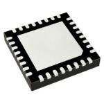 HMC892LP5ETR
The activity of extra discounts on wholesale prices is in full swing…
Please fill in your contact information and we will send you the latest wholesale price list.






